
Thomas Herrmann1*, Gerrick E. Lindberg1
1 Department of Chemistry and Biochemistry, Northern Arizona University, Flagstaff, Arizona
* taherrmann1@gmail.com
Abstract
Ionic liquids are a unique class of organic salts characterized by low melting points and high customizability. These solvents are composed of any anion and cation, so there are millions of unique combinations. Each pairing has its own specific properties that may be tuned for some application. Choline geranate (CAGE) is an ionic liquid that has been identified to possess antimicrobial effects. However, the exact mechanism is not well understood. To help explain this, molecular dynamics (MD) simulations were used to observe and understand the effect of CAGE on microbial structures. Specifically, the effects of CAGE on the polyomavirus KIPyV major capsid protein viral protein 1 (VP1) were simulated for signs of disruption of the viral protective shell. The interaction of CAGE with the KIPyV VP1 reveals a consistent promotion of α-helix secondary structure within surface loop regions. On average, simulations of the VP1 monomer show an increase in the proportion of α-helicity by 2.24%, which is 5 to 6 amino acid residues. Additionally, CAGE stabilizes existing α-helices within VP1. Because these surface loop areas of VP1 are responsible for host-cell infiltration and other critical viral functions, an increase in helical secondary structures may cause inhibition of processes necessary for replication. These findings contribute to the idea that CAGE may be used as a disinfectant that may be less toxic for humans and the environment.
Introduction
Ionic Liquids are a Diverse Class of Tunable Materials
The applications for easily tailored, well-characterized solutions extend into any field where solvent choice is relevant. However, adjusting traditional liquid solvents to fit specific niches requires a significant investment of time and expertise. Ionic liquids (ILs) offer an alternative answer: a liquid solution with unique properties depending on the ions selected. Like traditional salts, these solutions are primarily made up of a cation and anion component in known stoichiometric ratios. A wide variety of applications have called for the design of ILs, including solvent chemistry, electrochemistry, catalysis, analytical chemistry, lubricants, heat transfer, biofuels and many more (Greer et al. 2020; Krossing et al. 2006; Zhou et al. 2023). While this remains true, more thorough research revealed the inevitable downsides. These primarily include danger to the environment, especially in aquatic habitats (Greer et al. 2020).
As the name suggests, ILs are differentiated from other organic salts by being liquid at the temperature where they are used. Often, they are defined as having melting points below 100°C at standard pressure (Lei et al. 2017). This low melting point is commonly due to the branched, bulky shapes of component ions preventing tight, rigid organization as seen in other smaller salts.
While the safety of ILs is less important for some applications, their potential use in certain biological and commercial applications requires low toxicity. One common use case is in medicine as active pharmaceutical ingredients (API), known as API-ILs (Mitragotri 2024). Other applications exist, but all call for safe, non-toxic ILs. One candidate for this purpose is CAGE.
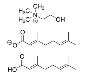
Figure 1. Structures of the component molecules of CAGE. Depending on the stoichiometric ratio of choline (top) and geranate (middle), geranic acid (bottom) will exist in equilibrium with its conjugate base. Because CAGE includes a major non-ion component, there is discussion over its classification as an IL or instead as a deep eutectic solvent Mitragotri (2024). These solutions are characterized by their hydrogen bond donors and acceptors. Additionally, they exist as a eutectic liquid, a mixture that has a significantly lower melting point than expected from the component compounds alone Hansen et al. (2020).
Developed in 2014, CAGE was the first IL intended for drug delivery to begin human clinical trials (Zakrewsky et al. 2014). It was investigated for its enhancement of both transdermal and oral pharmaceutical applications (Banerjee et al. 2018; Banerjee et al. 2017). Additionally, its use as a broad-spectrum antiseptic was proven effective on certain microbial species (Zakrewsky et al. 2016).
Viral Capsids and Major Capsid Proteins
In non-enveloped virus species, the viral capsid is a defining feature. The capsid is composed of a durable, multifunction protein shell involved in viral genome stabilization and eventual delivery, host cell infiltration and protection from the external environment (Roos et al. 2007). Capsids are composed of numerous repeating units of a viral capsid protein capable of self-assembly and reliable interaction with the viral genome (Louten 2016).
In 2007, a new strain of human polyomavirus was identified, named KIPyV (Allander et al. 2007). This virus is capable of persistent infection within the respiratory and gastrointestinal tracts, as well as other regions in the human body. The KIPyV capsid is icosahedral and composed of 72 pentameric copies of the major capsid protein VP1 (Neu et al. 2011). Therefore, 360 total copies of the VP1 monomer are responsible for receptor binding and antigen presentation, crucial functions of the capsid exterior. Supporting this framework are two more minor capsid proteins, VP2 and VP3. While these proteins are not necessary for self-assembly, their absence causes a significant decrease in pathogenicity (Ishiyama et al. 2024).
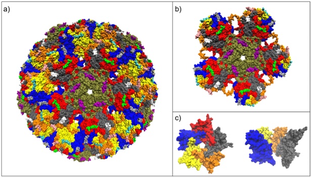
Figure 2. Surface representations of the murine polyomavirus capsid 1sie from Stehle and Harrison (1996). Panel a) depicts the full icosahedral capsid. Protein monomers are colored by chains (red, orange, blue, yellow, grey). Ligands (purple, light green) are included to demonstrate the repeating symmetry of the capsid. Panel b) shows a pentamer subunit attached to five neighboring pentamers. Panel c) further removes associated proteins to leave a single isolated pentamer subunit, with each monomer colored separately. A side view with a monomer removed illustrates the depth of the capsid.
At the core of the VP1 protein, a common supersecondary structure is observed. Named the ‘jelly-roll fold’, it is composed of eight antiparallel ꞵ-sheets in four pairs and makes up approximately 50% of all amino acids within VP1 (Neu et al. 2007). The structures are often labeled B through F, with sheets paired BIDG - CHEF (B pairs to C, I pairs to H, etc.). Loops are named by the strands where they begin and end. Several regions of interest are the internal-facing (CD loop), side-facing (EF loop) and, most importantly, exterior-facing structures (BC, DE and HI loops).
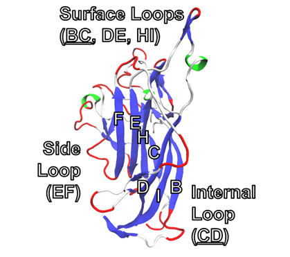
Figure 3. Cartoon diagram of the VP1 monomer, 3s7vB. β-sheets (dark blue) are annotated according to their corresponding letter within the BIDG - CHEF sequence. α-helices (light green) and bends (red) can be found in loop regions. The protein is oriented with the surface regions that are exposed to the external environment at the top of the image.
The external surface loops have been linked to host cell receptor binding interactions in human polyomavirus 1 (BKV), making them critical to virus replication (Dugan et al. 2007). KIPyV bears high sequence similarity within the coding regions of VP1 (Allander et al. 2007). The conservation of these sequences in viral species suggests that they are important for their lifecycle and their disruption might be a strategy to disrupt the virus.
Protein Structure and Dynamics can be Observed with Molecular Dynamics Simulations
Molecular dynamics (MD) has been an area of scientific interest since the first simulations of simple, hard-sphere gases in the late 1950s (Alder and Wainwright 1957). Modern MD simulations make use of computer processors and GPUs to perform calculations at incredible speed, accuracy and scale.
These advancements opened MD to many realms of science, including quantum mechanics, molecular biology, neuroscience, membrane simulations and many more (Hollington and Dror 2018). Specifically, the number of structural biology simulations more than doubled in the last 20 years, largely thanks to the ability of MD to track systems at atomic resolution. Additionally, a rise in accessibility, thanks to cloud computing and GPU-accelerated simulations, brought MD opportunities to teams without the funds to acquire an expensive supercomputer. The premise of MD is simple: for every atom in a given system, evaluate all forces acting on it by other nearby atoms and propagate its position using Newton’s laws of motion (Hollington and Dror 2018).
As discussed previously, the IL CAGE is shown to inhibit viral replication. However, the exact mechanism by which it accomplishes this is not well understood in laboratory environments. MD simulations are a useful method for extracting this information because the molecules of interest, while still quite large, can be efficiently run for short simulation timeframes. Specifically, the interactions of CAGE with the surface loops and the ‘jelly-roll’ core provide insight into its antiviral capabilities. Due to the customizable nature of ILs, obtaining additional details may lead to the development of a superior antiviral.
Methods
The Amber22 suite was used for all PDB preparation and GPU-accelerated MD simulations (Case et al. 2022a). The AmberTools programs used were pdb4amber, tleap and AddToBox (Case et al. 2022b). Simulations utilized SHAKE for all bonds with hydrogen (no force evaluation) with a tolerance of 0.0000001Å. A nonbonded cutoff of 12Å was used. To manage temperature and pressure in relevant simulations, the Langevin thermostat with a collision frequency of 2ps-1 and the Berendsen barostat with a pressure relaxation time of 1ps were utilized. Unless otherwise stated, simulations employed a constant pressure with isotropic periodic conditions with a time step of 2.5fs.
To prepare systems for simulation, the RCSB PDB file for 3s7v was processed using pdb4amber for use in Amber simulations (Neu et al. 2011). The desired structure (pentamer or monomer) was isolated using manual PDB file editing and VMD for confirmation. Next, an empty box was placed around the protein with enough clearance for solvent molecules (10Å for the pentamer and 5Å for the monomer simulations) using tleap with the protein.ff19SB forcefield for peptides, gaff2 general organic forcefield and optimal point charge (OPC) water force fields (Tian et al. 2019; Izadi et al. 2014; He et al. 2020). AddToBox was used to add the desired number of CAGE instances (50, 100 or 250) and then again to add the appropriate amount of water to reach 1M (55.55 water molecules per 1 CAGE). The resulting PDB was imported into tleap to generate Amber parameter and input coordinate files.
Running a sequence of minimizations relaxed the system and eliminated excessively high energies due to improper atom overlap encountered when building the system, while a Python script was used to generate the file structure and input files. Twenty 2000-step minimizations were run, switching from steepest descent to conjugate gradient after 1000 steps. In the first minimization, all protein and water atoms were harmonically restrained with a force constant of 10kcal mol-1 Å-2. After the first minimization, the restraints were linearly stepped down from 10 to 0kcal mol-1 Å-2. The last 10 minimizations used no restraints. The final output files were examined for appropriately large, negative energies.
After minimization, the system was brought up to 310K in a constant volume simulation with a time step of 0.5fs. The run began at 0K and was linearly ramped to 310K over 0.1ns. In the next simulation, the system was held at 310K for 4ns under standard simulation conditions. Due to the large changes in box size as a result of poor packing by AddToBox, GPU-accelerated simulations required several restarts using the last available restart file. However, once the system converged on an appropriate density, no further restarts were needed.
To equilibrate the system, a 2ns simulation was run with the protein backbone harmonically restrained with a force constant of 0.2kcal mol-1 Å-2 and side chains by 0.1kcal mol-1 Å-2. To bring the simulation to an appropriate pressure, a 1atm barostat was applied. The second equilibration was another 2ns simulation without restraints. Finally, the system was run for forty 100ns production runs. Analysis of these production simulations is reported in this work.
Preparation and analysis of the simulation trajectories were performed with the CPPTRAJ utility in the Amber suite. Qualitative observation of protein systems was performed with VMD using the sscache script, allowing for real-time updates to protein secondary structure (Humphrey et al. 1996). Secondary structure classification was performed using the Dictionary of Secondary Structure of Proteins (DSSP), which utilizes an algorithmic analysis of intra-backbone H-bonds to identify secondary structure (Joosten et al. 2010; Kabsch and Sander 1983). To create the secondary structure graphs, the DSSP secstruct function in CPPTRAJ was used to produce the data, which was then formatted using gnuplot (Williams and Kelley 2023). For the % DSSP graphs, the DSSP value of each residue was tallied and normalized to the total number of residues for each frame.
Results
The VP1 monomer exhibits stable secondary structures independent of the pentamer.
Analysis of secondary structure graphs provided insight into the location and form of structures of interest. Qualitative analysis of the protein’s ‘jelly-roll’ core showed little change in structure in both monomer and pentamer simulations. While the β-sheets that primarily make up the core of the protein remained stable, other structural motifs were observed to change. These changes in water and aqueous CAGE were examined in subsequent sections.
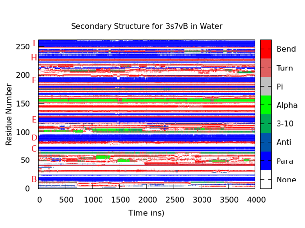
Figure 4. Secondary structure for 3s7vB in water. At each step, all residues were assigned a DSSP secondary structure and a corresponding color. The protein core is easily identified by the large bands of parallel β-sheets (dark blue) that remain stable through the simulation. The names of the β-sheets corresponding to their location within the ‘jelly-roll’ core are identified in red letters on the left. The ‘G’ β-sheet is mostly absent in KIPyV VP1. As expected, the BC loop (residues 25 - 68) lacks large, consistent secondary structures. A stable α-helix (bright green) is seen (residues 151 - 156) that lasts for the entire simulation. A similar structure is observed earlier in the protein (residues 99 - 105), but it loses its structure around 2000ns.
CAGE promotes α-helix formation in VP1.
Simulations of 3s7vB in water and CAGE revealed a notable increase in α-helicity. However, detailed assessment of amino acid participation in secondary structure was difficult to interpret. By tracking secondary structure across the whole protein instead of each residue, a clearer picture of the size of α-helix formations was observed. Therefore, for each %DSSP graph, all residues belonging to a certain secondary structure were summed and normalized for each step. Condensing thousands of data points into simple lines creates a significant amount of noise. To minimize this, a simple running average was used.

Table 1. Averaged proportions of α-helicity within 3s7v simulations. Values were obtained by obtaining the mean proportion of α-helicity across the designated timeframe.
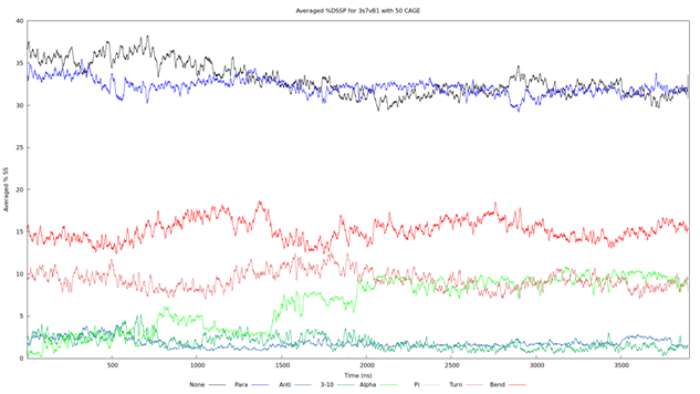
Figure 5. Averaged %DSSP graph for 3s7vB1 with 50 CAGE. The color of each line corresponds to the same secondary structures as seen in Figure 4 and other secondary structure graphs. The trial began with an α-helix proportion of approximately 2% and has two notable increases. The first appears around 600ns but then relaxes. A larger increase is seen at 1450ns with a climb to approximately 10% that remains steady for the remainder of the simulation.
Surface regions of VP1 are especially prone to α-helix formation.
All five 3s7vB simulations exhibited the same conserved α-helices, although to varying degrees. In 3s7vB4, the α-helix covering residues 99 - 105 lost stability after 250ns and did not regain its structure. The α-helix covering residues 151 - 156 was consistently shorter in 3s7vB simulations 2 and 5 by approximately 2 amino acids. Other α-helices were observed in certain simulations as well. In 3s7vB simulations three and five, an α-helix covering residues 205 - 210 appeared during the simulation and remained stable until the end.
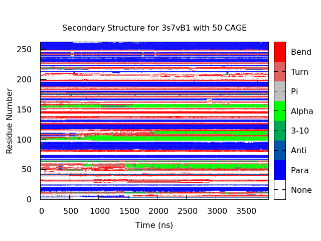
Figure 6. Secondary structure for 3s7vB1 with 50 CAGE. The same dark blue bands can be matched to the β-sheet naming in Figure 4. Additionally, two α-helices are observed to form and persist (residues 99 - 105 and 151 - 156). The former of which displays increased stability and size compared to its appearance in Figure 4. Two new α-helices are seen (residues 52 - 58 and 107 - 112) that each display a similar level of stability to the conserved structures. All four of these structures exist within either the BC or DE surface loops.
Discussion
CAGE and VP1 are representative of broader systems.
Viral capsid proteins are designed to both withstand the external environment and protect their contents in a wide range of conditions. While common disinfectants are effective at disrupting and denaturing these proteins, less toxic options could minimize the harm to the person applying them and the environment in which they are used. CAGE, with its non-toxic components, offers a potential solution to this issue. Not only has the IL seen promise in human drug trials, but it also avoids the significant harmful chemical and health byproducts generated by other disinfectants. However, its mode of action as an antimicrobial agent is not well understood. The MD simulations presented in this paper predict a disruptive effect of CAGE on the viral capsid protein VP1.
Before any analysis of change within the secondary structure can be performed, an understanding of the normal behavior of the protein in its monomer and pentamer forms is necessary. Observing the unmodified behavior of VP1 within an MD simulation can serve as a reference point to later understand the effects of CAGE. VP1 self-assembles into 72 pentamer structures that further link to form the icosahedral viral capsid (Figure 2). However, simulating an entire capsid at full resolution requires the simulation of over 1.4 million atoms, an extremely slow proposition. Even a single pentamer is composed of over 20,000 atoms, excluding solvent and a 4μs simulation requires around 40 days on Monsoon, the supercomputer at Northern Arizona University. Therefore, when designing this experiment, we focused on the VP1 monomer as an appropriate representative system where relevant structure is maintained while still being representative of the larger assembly. The monomer exhibits this stability within its core structures. The seven ꞵ-sheets composing the ‘jelly-roll’ core are clearly identifiable as stable blue bands. While infrequent fluctuations in the amino acids near the ends of the sheets are observed, these are transient and limited to a change of one residue. In addition, significant secondary structure, including two conserved α-helices, also shows notable stability within the disordered loop regions. First, the general stability of the VP1 monomer in water confirms the viability of our approach to understanding the viral shell with this simplified system. Second, these secondary structure features could be used as landmarks to aid later interpretation of results with CAGE
CAGE promotes α-helix formation in VP1.
The structure-function paradigm states that the structure of a protein is directly related to its function. Any disruptions to this structure can result in dramatic changes to function, with many alterations rendering the protein inactive. The most dramatic of these is denaturation. Whether by heat, pH or other factors, a denatured protein is no longer in its active structure and cannot perform its biological function. At the tested concentration of CAGE, denaturation is not observed, which could be beneficial for deployment in and around living organisms. Nevertheless, CAGE is observed to produce an observable change in secondary structure in VP1.
By investigating the proportion of each DSSP secondary structure over time, a notable increase in α-helicity is observed while other secondary structural motifs change only minimally (Figure 5). Further simulations contribute to this finding with 3s7vB CAGE simulations displaying an inconsistent but overall average increase in α-helicity (Table 1). The most common structure by residue count is the ꞵ-sheet. The prevalence of ꞵ-sheets is expected because of the large ‘jelly-roll core’. This observation lends credit to the stability of the protein overall as a complete loss of structure due to CAGE or other instabilities would result in massive changes to all secondary structures, especially the ꞵ-sheet core. Previous MD studies on ILs observed similar increases in α-helicity in a variety of biological proteins, including bacterial, viral and others (Carter et al. 2019; Takekiyo et al. 2013). A potential correlation may be drawn between the antimicrobial effects seen in lab environments and the consistent promotion of α-helicity observed in MD simulations.
Furthermore, the locations of new α-helices are most frequently observed in surface regions of the protein. The BC surface loop is the largest loop in 3s7v and has been linked to host-cell receptor binding, an essential viral function (Gee et al. 2004). It is mostly disordered with small turns and bends dotting its length. Two α-helices conserved from the 3s7vB water simulation appear in all five 3s7vB CAGE simulations and make up most of the average 2.87% starting α-helix proportion described in Table 1. The source of the average 2.24% increase is less consistent. In 3s7vB simulations 1, 3 and 5, a third α-helix is seen over residues 52 – 58. This structure is most clearly observed in 3s7vB1 with 3s7vB simulations three and five also displaying this structure but with significantly less stability (Figure 4). 3s7vB1 presents a second stable α-helix over residues 107 – 112 but is the only run to do so. A final α-helix covering residues 205 – 210 is seen in 3s7vB simulations three and five which presents similar stability and size to the conserved helices found in all simulations. However, this region does not correspond to any of the defined surface loops, instead appearing near the FG or GH regions. These areas are not openly exposed to the external environment in the assembled capsid.
Overall, a slight but observable increase in α-helicity is seen in the surface regions of VP1 when exposed to CAGE. While these changes are generally small relative to existing structures, their repeated appearance suggests a correlation with CAGE. Despite this, the changes in α-helicity within functional regions may conflict with the mechanism for host-cell binding or other functions necessary for viral replication. Especially due to their consistent promotion within the surface loop regions, these simulations may bridge the gap between the antimicrobial observations of CAGE and its method of action.
Validity of results and the theory of ergodicity.
Further simulations that test various experimental conditions would help clarify the results presented here. For example, altering the concentration of CAGE, testing additional 3s7v monomers and running additional controls would clarify the exact role of CAGE and how it interacts with VP1. While the average increase reported in Table 1 is notable, it possesses a high standard deviation due to the scarcity of data points and inconsistency of α-helix formation across simulations. The total range of α-helicity increases is 6.37%, slightly less than three times the average. This is mostly due to 3s7vB simulation two presenting no increase overall when exposed to CAGE despite retaining all the other behavior seen in the other simulations. To explain this, a common theory within MD is that of ergodicity. Ergodicity is the idea that given enough time, a dynamic system composed of an arbitrary number of substates will demonstrate the same average results as an ensemble of systems measured together (Pearson 2025). For example, the proportion of heads of a coin flipped enough times will reach 50%, the same average result as flipping many coins simultaneously. Unfortunately, running a simulation for such a long period of time or running many simulations is a challenging test of resources and time. A defense of the absence of α-helix increase in simulation two and the large standard deviation in other systems in general is that the systems have not had enough time to reach the same ensemble average, nor are there enough data points to produce one. Increasing the number of simulations or running them for longer than 4µs will further determine the repeatability of results.
All classical MD simulations rely on force fields, a set of parameters that define the forces between every pair of atoms in the system. These parameters are approximations of atomic interactions, such as electrostatic potentials, spring constants and others. They are typically based on calculated results from quantum mechanics and/or empirical data. However, there are limitations to the technique.
Despite great improvements in accuracy, force fields remain as approximations as the computing power required to fully evaluate all quantum mechanical equations for systems of this size is computationally intensive and usually limited to much smaller systems. In the simplest circumstance, the computing power required for a classical MD simulation scales with the number of atoms squared (n2, where n is the number of atoms). Quantum mechanical MD simulations typically scale cubically (n3) at best. Hybrid techniques exist that simulate a few specific electrons of interest quantum mechanically while modeling other regions classically or with a cheaper level of theory (Brunk and Rothlisberger 2015). However, when attempting to assess a solvent’s interaction across an entire protein, these combined techniques are difficult to employ while remaining physically meaningful. Despite this, the predictions from classical MD simulations offer significant opportunities for exploring behaviors that would be challenging or impossible to otherwise observe.
Overall, CAGE shows promise as a novel disinfectant that demonstrates antimicrobial properties while exhibiting minimal toxicity to the surrounding environment. The simulations detailed in this work offer a potential explanation for the results seen in CAGE’s original discovery by Zakrewsky et al. in 2014. Because ILs may be composed of any two component ions whose mixed melting point remains a liquid at room temperature, related materials may act as superior disinfectants. By considering the results regarding α-helicity discussed in this experiment, continued improvements may be made with secondary structure formation as a basis. Building ILs with a specific function in mind eliminates an immense number of inefficient combinations, greatly increasing the rate of their development towards an effective, nontoxic disinfectant.
Acknowledgements
We acknowledge Andrew Koppisch for helpful discussions that guided us toward this project. Computational analyses were run on Northern Arizona University’s Monsoon computing cluster, funded by Arizona’s Technology and Research Initiative Fund (TRIF). Partial funding for the project was provided by the National Aeronautics and Space Administration (NASA) cooperative agreement 80NSSC20M0041. This work was supported through a NASA grant awarded to the Arizona/NASA Space Grant Consortium. Any opinions, findings, conclusions or recommendations expressed in this material are those of the authors and do not necessarily reflect the views of NASA. Additional funding was provided by the office of the Northern Arizona University Vice President for Research as Student Mentored Research Training, funded by TRIF.
References
Alder, B.J. and Wainwright, T.E. (1957). ‘Phase transition for a hard sphere system’, The Journal of Chemical Physics, 27(5), pp. 1208–1209. doi:10.1063/1.1743957.
Allander, T., Andreasson, K., Gupta S., Bjerkner, A., Bogdanovic, G., Persson, M., Dalianis, T., Ramqvist, T., and Andersson, B. (2007). ‘Identification of a third human polyomavirus’, Journal of Virology,81(8), pp. 4130–4136. doi:10.1128/jvi.00028-07.
Banerjee, A., Kelly, I., Yasunori, I., Zakrewsky, M., and Mitragotri, S. (2017). ‘Transdermal protein delivery using choline and Geranate (cage) deep eutectic solvent’, Advanced Healthcare Materials, 6(15). doi:10.1002/adhm.201601411.
Banerjee, A., Ibsen, K., Brown, T., Chen, R., Agatemor, C., and Mitragotri, M. (2018). ‘Ionic liquids for oral insulin delivery’, Proceedings of the National Academy of Sciences, 115(28), pp. 7296–7301. doi:10.1073/pnas.1722338115.
Brunk, E., Rothlisberger, U. (2015). ‘Mixed quantum mechanical/molecular mechanical molecular dynamics simulations of biological systems in ground and electronically excited states’, Chemical Reviews, 115(12), 6217–6263.
Carter, E., Heyert, A., Souza, M., Baker, J., and Lindberg, G. (2019). ‘The ionic liquid [C4mpy][tf2n] induces bound-like structure in the intrinsically disordered protein flgm’, Physical Chemistry Chemical Physics, 21(32), pp. 17950–17958. doi:10.1039/c9cp01882d.
Case, D., Aktulga, M., Belfon, K., Ben-Shalom, I., Brozell, S., Cerutti, D., Cheatham, T., Cisneros, G., Cruzerio, V., Darden, T., Duke, R., Giambasu, G., Gilson, M., Gohlke, H., Götz, A., Harris, R., Izadi, S., Izmailov, S., and Kollman, P. (2022a). ‘Amber 2022’
Case, D., Aktulga, M., Belfon, K., Ben-Shalom, I., Brozell, S., Cerutti, D., Cheatham, T., Cisneros, G., Cruzerio, V., Darden, T., Duke, R., Giambasu, G., Gilson, M., Gohlke, H., Götz, A., Harris, R., Izadi, S., Izmailov, S., and Kollman, P. (2022b). ‘AmberTools’, J. Chem. Inf. Model, 63, pp. 6183-619. doi:https://doi.org/10.1021/acs.jcim.3c01153
Dugan, A., Gasparovic, M., Tsomaia, N., Mierke, D., O’Hara, B., Manley, K., and Atwood, W. (2007). ‘Identification of amino acid residues in BK virus VP1 that are critical for viability and growth’, Journal of Virology, 81(21), pp. 11798–11808. doi:10.1128/jvi.01316-07.
Gee, G., Tsomaia, N., Mierke, D., and Atwood, W. (2004). ‘Modeling a sialic acid binding pocket in the external loops of JC Virus VP1’,Journal of Biological Chemistry, 279(47), pp. 49172–49176. doi:10.1074/jbc.m409326200.
Greer, A., Jacquemin, J., and Hardacre, C. (2020). ‘Industrial applications of ionic liquids’,Molecules, 25(21), p. 5207. doi:10.3390/molecules25215207.
Hansen, B., Spittle, S., Chen, B., Poe, D., Zhang, Y., Klein, J., Horton, A., Adhikari, L., Zelovich, T., Doherty, B., Gurkan, B., Mahinn, E., Ragauskas, A., Dadmun, M., Zawodzinski, T., Baker, G., Tuckerman, M., Savinell, R., and Sangoro, J. (2020). ‘Deep eutectic solvents: A review of fundamentals and applications’,Chemical Reviews, 121(3), pp. 1232–1285. doi:10.1021/acs.chemrev.0c00385.
He, X., Man, V., Yang, W., Lee, T, and Wang, J. (2020). ‘A fast and high-quality charge model for the next generation General Amber Force Field’, The Journal of Chemical Physics, 153(11). doi:10.1063/5.0019056.
Hollingsworth, S.A. and Dror, R.O. (2018). ‘Molecular dynamics simulation for all’, Neuron,99(6), pp. 1129–1143. doi:10.1016/j.neuron.2018.08.011.
Humphrey, W., Dalke, A. and Schulten, K. (1996). ‘VMD: Visual molecular dynamics’,Journal of Molecular Graphics, 14(1), pp. 33–38. doi:10.1016/0263-7855(96)00018-5.
Ishiyama, R., Yoshida, K., Oikawa, K., Takai-Todaka, R., Kato, A, Kanamori, K., Nakanishi, A., Haga, K., and Katayama, K. (2024). ‘Production of infectious reporter murine norovirus by VP2 trans-complementation’,Journal of Virology, 98(2). doi:10.1128/jvi.01261-23.
Izadi, S., Anandakrishnan, R. and Onufriev, A.V. (2014). ‘Building water models: A different approach’, The Journal of Physical Chemistry Letters, 5(21), pp. 3863–3871. doi:10.1021/jz501780a.
Joosten, R., te Beek, T., Krieger, E., Hekkelman, M., Hooft, R., Schneider, C., and Vriend, G. (2010). ‘A series of PDB related databases for everyday needs’, Nucleic Acids Research, 39(Database). doi:10.1093/nar/gkq1105.
Kabsch, W. and Sander, C. (1983). ‘Dictionary of protein secondary structure: Pattern recognition of hydrogen‐bonded and geometrical features’, Biopolymers, 22(12), pp. 2577–2637. doi:10.1002/bip.360221211.
Krossing, I., Slattery, J., Daguenet, C., Dyson, P., Olenikova, A., and Weingärtner, H. (2006). ‘Why are ionic liquids liquid? A simple explanation based on lattice and solvation energies’, Journal of the American Chemical Society, 128(41), pp. 13427–13434. doi:10.1021/ja0619612.
Lei, Z., Chen, B., Koo, Y., and MacFarlane, D. (2017). ‘Introduction: Ionic liquids’, ChemicalReviews, 117(10), pp. 6633–6635. doi:10.1021/acs.chemrev.7b00246.
Li, M., Delos, S., Montross, L., and Garcea, R. (1995). ‘Polyomavirus VP1 phosphorylation: Coexpression with the VP2 capsid protein modulates VP1 phosphorylation in SF9 insect cells.’, Proceedings of the National Academy of Sciences, 92(13), pp. 5992–5996. doi:10.1073/pnas.92.13.5992.
Liddington, R., Yan, Y., Moulai, J., Sahli, R., Benjamin, T., and Harrison, S. (1991). ‘Structure of simian virus 40 at 3.8-Å resolution’, Nature,354(6351), pp. 278–284. doi:10.1038/354278a0.
Louten, J. (2016). ‘Virus structure and classification’, Essential Human Virology, pp. 19–29. doi:10.1016/b978-0-12-800947-5.00002-8.
Mitragotri, S. (2024). ‘Choline Geranate (cage): A multifaceted Ionic liquid for drug delivery’, Journal of Controlled Release, 376, pp. 593–600. doi:10.1016/j.jconrel.2024.10.034.
Neu, U., Wang, J., Macejak, D., Garcea, R., and Stehle, T. (2011). ‘Structures of the major capsid proteins of the human Karolinska Institutet and Washington University polyomaviruses’, Journal of Virology, 85(14), pp. 7384–7392. doi:10.1128/jvi.00382-11.
Roos, W., Ivanovska, I., Evilevitch, A., and Wuite, G. (2007). ‘Viral capsids: Mechanical characteristics, genome packaging and delivery mechanisms’, Cellular and Molecular Life Sciences, 64(12). doi:10.1007/s00018-007-6451-1.
Stehle, T. and Harrison, S.C. (1996). ‘Crystal Structures of murine polyomavirus in complex with straight-chain and branched-chain sialyloligosaccharide receptor fragments’,Structure, 4(2), pp. 183–194. doi:10.1016/s0969-2126(96)00021-4.
Takekito, T., Koyama, Y., Yamazake, K., Abe, H., and Yoshimura, Y. (2013). ‘Ionic liquid-induced formation of the α-helical structure of β-lactoglobulin’, The Journal of Physical Chemistry B, 117(35), pp. 10142–10148. doi:10.1021/jp405834n.
Taylor Pearson (2025). A big little idea called ergodicity (or the Ultimate Guide to Russian Roulette), Taylor Pearson. Available at: https://taylorpearson.me/ergodicity/#:~:text=What%20is%20Ergodicity?,are%20typically%20not%20ergodic)! (Accessed: 31 March 2025).
Tian, C., Kasavajhala, K., Belfon, K., Raguette, L., Huang, H, Migues, A., Bickel, J., Wang, Y., Pincay, J., Wu, Q., and Simmerling, C. (2019). ‘FF19SB: Amino-acid-specific protein backbone parameters trained against quantum mechanics energy surfaces in solution’, Journal of Chemical Theory and Computation, 16(1), pp. 528–552. doi:10.1021/acs.jctc.9b00591.
Williams, T. and Kelley, C. (2023). Gnuplot 6,Gnuplot. Available at: https://gnuplot.sourceforge.net/ (Accessed: 14 April 2025).
Zakrewsky, M., Lovejoy, K., Kern, T., Miller, T., Le, V., Nagy, A., Goumas, A., Iyer, R., Del Sesto, R., Koppisch, A., Fox, D., and Mitragotri, S. (2014). ‘Ionic liquids as a class of materials for transdermal delivery and pathogen neutralization’, Proceedings of the National Academy of Sciences, 111(37), pp. 13313–13318. doi:10.1073/pnas.1403995111.
Zakrewky, M., Banerjee, A., Apte, S. Kern, T., Jones, M., Del Sesto, R., Koppisch, T., Fox D., and Mitragotri, S. (2016). ‘Choline and geranate deep eutectic solvent as a broad‐spectrum antiseptic agent for preventive and therapeutic applications’, Advanced Healthcare Materials, 5(11), pp. 1282–1289. doi:10.1002/adhm.201600086.
Zhout, T., Gui, C., Sun, L., Hu, Y., Lyu, H. Wang, Z. Song, Z., and Yu, G. (2023). ‘Energy applications of ionic liquids: Recent developments and future prospects’, Chemical Reviews, 123(21), pp. 12170–12253. doi:10.1021/acs.chemrev.3c00391.