
Author: Donald H. Kuettel III
Institution: Milwaukee School of Engineering, 1025 N. Broadway, Milwaukee, WI 53202
doi: 10.22186/jyi.31.5.32-38
ABSTRACT
Active orthotic devices for joint articulation have a vast number of applications that could benefit many people. Examples include joint articulation for people suffering from disabilities, increased load carrying capacity and walking distance for humans, and gait training. The main goal of this research is to help people with disabilities regain natural walking ability by replicating normal walking gait through the use of an active ankle-foot orthosis (AAFO). This research investigates the optimization of a pulley system for the primary actuator of an AAFO utilizing a high-efficiency pneumatic “Walking Engine.” In order to accurately replicate a healthy human gait, the AAFO device had to accurately reproduce the moment applied to the ankle during the gait cycle. The AAFO’s internal-combustion (IC) engine was characterized using a dual-combustion (limited-pressure) gas-power-cycle model. With the dual-combustion model, both a theoretical pressure-volume diagram and the thermodynamic engine efficiency were calculated. Using the calculated pressure output of the IC engine, the pulley system was optimized to best match the ankle moment of a healthy human gait, which was obtained from David Winter’s Biomechanics and Motor Control of Human Movement. The optimized pulley geometry is very complicated and additional research is necessary to utilize its design. The results of this research provide insight for the future development of untethered, lightweight, efficient AAFO devices.
INTRODUCTION
With increasing advancements in robotics technology, robotic systems, such as the Walking Engine, are continuously being implemented in new and exciting ways. As a result, humans experience ever increasing interactions with robotic systems on both a professional and personal level. On the personal level, these robotic systems can be used to assist with physical impairment, amplify normal physical capabilities, and even act as an extension of human abilities for the 35.2 million people suffering from physical functioning disabilities (Dollar & Herr, 2007). Some well-publicized examples include the systems being developed by Boston Dynamics for assisting military personnel in carrying equipment (Big Dog, Little Dog) and exoskeletons that provide walking assistance for those normally bound to wheel chairs for mobility (ReWalk, EKSO) (Dollar & Herr, 2007). The main goal of this research is to design an active ankle-foot orthosis (AAFO) that helps people with disabilities regain natural walking ability by replicating the normal walking gait of a human. This paper investigates the combination of robotic system technology and orthotics in the form of an AAFO to accomplish this goal.
Active Ankle-Foot Orthosis
Orthotics is a specialty within the medical field concerned with the design, manufacture, and application of an orthosis. An orthosis is an externally applied device used to modify the structural and functional characteristics of the neuromuscular and skeletal system (Lusardi, Jorge, & Nielson, 2013). Orthotic devices can be designed to control, guide, limit, or immobilize an extremity, joint, or body segment. Under the International Standard terminology, orthoses are classified by an acronym describing the anatomical joints that they contain (Lusardi et al., 2013). For example, an orthosis applied to the ankle and foot, such as the one investigated in this research, is an ankle-foot orthosis (AFO). AFOs are commonly used in the treatment of disorders that affect muscle function such as stroke, spinal cord injury, muscular dystrophy, cerebral palsy, polio, multiple sclerosis, and peripheral neuropathy by: providing artificial joint articulation, increasing load-carrying capabilities; and, assisting in gait-training procedures (i.e. people re-learning to walk from an injury or disability) (Lusardi et al., 2013).
Currently, ankle-foot orthoses fall into the two main categories of passive and active (powered) orthoses. Figure 1 shows a comparison of a passive and active AFO system. Passive AFOs rely on an external energy source (the user) and either utilize mechanical components, such as springs, to assist with movement, or are rigid and simply immobilize the joint (Lusardi et al., 2013). Passive devices are typically lightweight with simple designs, resulting in low cost and high robustness. However, despite their benefits, many problems exist in current passive AFO designs. While most patients see improvement with their ability to walk with the aid of these devices, the gait is labored and very unnatural (Lenhart & Sumarriva, 2008). AAFO devices seek to combat this limitation by replicating human gait with an integrated power source. AAFOs are typically powered using a pneumatic or electric power source (Lusardi et al., 2013). This integrated power source allows for more precise movement and complex functionality of the ankle joint. This complexity adds extra weight and size to the apparatus (Figure 1). One major shortcoming of current AAFO designs is this tradeoff between size and functionality. An ideal AAFO design must be compact and lightweight, in addition to having the capability for the complex functions needed to accurately replicate human gate. The issue of complexity versus weight can be addressed by using an internal-combustion (IC) engine, such as a “Walking Engine”, to power the device.
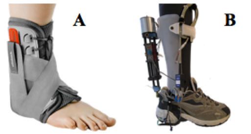
Figure 1: Passive vs. Active Ankle-Foot Orthosis. This figure shows a comparison of a passive (A) and active (B) AFO. Passive AFOs simply immobilize the ankle and foot while active AFOs assist the ankle and foot in replicating human gait (Blackwell, Lucas, & Clarke, 2014).
High Efficiency Pneumatic Walking Engine
It is understood that hydrocarbon fuels have a much higher specific energy than electric batteries or compressed air (Mitchell, Gallant, Thompson, & Shao-Horn, 2011). While liquid petroleum gases, such as butane, propane, or methane, have specific energies of around 45-50MJ/kg, electric batteries have specific energies of only around 9-10MJ/kg. Since a compact and lightweight design is required, an AAFO utilizing a small IC engine as the primary means of ankle articulation was chosen for this research. Propane, a common liquid petroleum gas, was selected as the IC engine’s fuel source due to its associated ease of implementation and high energy density.
To further meet the efficient and lightweight AAFO design requirements, an IC “Walking Engine” was chosen over a typical IC engine due to its increased thermodynamic and system efficiency. In a typical IC engine, a portion of the energy obtained from combustion is used to compress the engine’s pistons with the use of a flywheel. Consequently, this energy does not contribute to the forward motion of the vehicle. On the contrary, with a “Walking Engine” the user of the AAFO can be viewed as the flywheel. The kinetic energy from the forward motion of the user also supplies the energy to compress the pistons, providing much higher system efficiency. Thermodynamically speaking, a typical IC engine converts merely 25% of the applied fuel energy into usable energy, suffering losses from exhaust (40%), coolant (30%), and friction (5%) (Heywood, 1988). Conversely, a “Walking Engine” converts a substantial 55% of the applied fuel energy into usable energy. This is accomplished with the implementation of a passive cooling system and reusing recovered exhaust energy in a pneumatic system.
A design for an AAFO has been developed that utilizes a forced-induction, “Walking Engine” actuation system, as shown in Figure 2. The design employs two opposing (antagonistic), asymmetric piston actuators to provide the required power for locomotion. The primary actuator is driven by a forced-induction, propane-powered, IC “Walking Engine”. Exhaust energy from the combustion engine is captured to charge a pneumatic system that will drive the second actuator.
The two grey cylinders shown in Figure 2 are the two actuating pistons. On the left is the primary actuator, which is the IC engine and provides the power required for the plantarflexion phase of the gait cycle. The green object in the schematic represents the fuel canister, while the blue tube represents the surrounding air. The fuel and the air will be forced into the combustion chamber with a hydraulic bellows pump. The bellows pump is shown under the heel of the foot bed. For ignition, a spark plug device will be activated, creating a spark. The exhaust from the engine is shown on the diagram as the red area connecting the primary cylinder to the secondary cylinder. The energy from the engine exhaust is captured and used to pneumatically power the secondary actuator. The secondary actuator provides the power for the dorsiflexion phase of the gait cycle. This design represents the optimal compromise between size, weight, and power.

Figure 2: Walking-Engine-Actuated Active Ankle-Foot Orthosis. A conceptual schematic of a Walking Engine AAFO is presented. The AAFO is powered by an internal-combustion engine using two opposing (antagonistic), asymmetric, piston actuators to provide the required power for locomotion.
MATERIALS AND METHODS
The main goal of this research is to help people with disabilities regain natural walking ability by replicating the normal walking gait of a human through the use of an AAFO device. We investigated the optimization of a pulley system for the primary actuator of an AAFO utilizing a high-efficiency pneumatic “Walking Engine”. To accurately replicate a healthy human gait, the AAFO device had to properly reproduce the moment applied to the ankle during that gait. Thus, the IC engine used on the AAFO had to be properly characterized. Once the IC engine’s performance was accurately modeled, a pulley system was optimized to best match the ankle moment of a healthy human gait.
Walking Engine Characterization
The IC engine used as the “Walking Engine” in the AAFO device was a pre-manufactured, or off-the-shelf (OTS), Bosch pneumatic actuator (Bosch, Stuttgart, Germany). The OTS actuator, having an inner chamber diameter of 25mm and a maximum piston extension of 50mm, was modified for use as an IC engine. Figure 3 shows a computer-aided design (CAD) model of the modified OTS Bosch actuator.

Figure 3: Walking Engine. This figure shows a CAD model of the modified Bosch pneumatic actuator used to power the AAFO. By adding a fuel line (needle valve) and ignition source (spark plug), an off-the-self pneumatic actuator was turned into a small IC engine.
To convert the Bosch actuator into an operational IC engine, several modifications were necessary. First, a hole was drilled into the bottom of the actuator to allow for the insertion of the spark plug ignition source. A block extension was then added to the bottom of the actuator to ensure that the actuator could withstand the stresses generated from the 10:1 compression ratio combustion. A metal piston extension was also added to the bottom of the actuator’s piston to protect the rubber-sealing device from the flames generated during combustion. Finally, for experimental combustion testing, a needle valve was attached to the bottom actuator port to allow the fuel/air mixture in, hold the pressure during compression and combustion, and allow the exhaust gas to escape the engine chamber.

Figure 4: Dual-Combustion Engine Cycle. This figure shows the theoretical thermodynamic engine cycle (dual-combustion cycle) used to model the AAFO’s internal-combustion engine. A dual-combustion engine cycle is a combination of both the Otto and the Diesel engine cycle (Heywood, 1988).
Gas-Power-Cycle Calculation
The first step in characterizing the IC engine used on the AAFO was to calculate the gas power cycle for the engine. A gas power cycle, or thermodynamic engine cycle, consists of a linked sequence of thermodynamic processes that involve the transfer of heat and work into and out of the engine system that eventually returns the system to its initial state (Heywood, 1988). Each thermodynamic engine cycle for the AAFO engine corresponds to one step of the leg equipped with the device during the gait cycle (i.e., one cycle per step by the leg that wears the device). A pressure-volume diagram is often used to represent the thermodynamic cycle of an engine. A dual-combustion (limited-pressure) pressure-volume diagram was chosen to model the gas power cycle of the IC engine used to power the AAFO.
A dual-combustion engine cycle is a combination of both the Otto and the Diesel engine cycle (Heywood, 1988). Energy from combustion is added as heat in two different stages, q1’ and q1”(Figure 4). Heat addition occurs first at a constant volume, similar to the Otto cycle, and then at a constant pressure, resembling the Diesel cycle. A dual-combustion cycle was chosen to represent the AAFO’s IC engine because this cycle is a closer approximation to the real life behavior of IC engines. In typical applications, the combustion process of an IC engine does not occur perfectly at a constant volume or a constant pressure, but rather in two separate stages as indicated by the dual cycle (Heywood, 1988).
When calculating the gas power cycle of the “Walking Engine” some important assumptions about the engine process were made in order to simplify the calculations. The first major assumption, which is assumed in most engine cycles, is that the working fluid (the air/fuel mixture) of the engine remains in a gaseous state throughout the cycle. It is also assumed that the working fluid can be modeled solely as air and can always be treated as an ideal gas. Furthermore, this research assumes an ideal engine cycle in which internal irreversibilities and other complexities, such as the combustion process and the exhaust of the products of combustion, are removed (Heywood, 1988).
In addition to these initial assumptions, the IC engine cycle was approximated with the following assumptions.
⋅ All of the engine processes listed in Figure 4 are internally reversible.
⋅ A dual-heat-addition process from an external source replaces the combustion process.
⋅ The lower heating value (LHV; 2044kJ/mol) of propane was used with an 80% burn efficiency during combustion calculations (Linstrom & Mallard, 2001).
⋅ A perfect stoichiometric air/fuel mixture was also used for the combustion calculations.
Thermodynamic Engine Efficiency
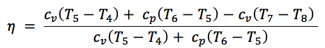
The second step in characterizing the IC engine used to power the AAFO was to calculate the thermodynamic efficiency of the engine. The thermodynamic efficiency of an engine is a dimensionless relationship between the total energy supplied to the engine—through the combustion of fuel—and the amount of energy available to perform useful work (Heywood, 1988). In other words, thermodynamic efficiency indicates how well an energy conversion process is accomplished. The thermodynamic efficiency of a dual-combustion engine cycle is represented by Equation 1:

(Eq. 1)
where, as Figure 4 shows, q1’ is heat addition at a constant volume, q1” is heat addition at a constant pressure, and q2 is heat rejection during exhaust. By using the fact that an energy exchange can be modeled by heat capacity, q1’, q1”, and q2 can be rewritten as the following:

(Eq. 2)
By substituting in these relations, Equation 1 can be rewritten in the following, more convenient form:
(Eq. 3)
Thus, the thermodynamic efficiency of the IC engine used to power the AAFO can be calculated using Equation 3 and the temperatures found from the gas power cycle. It is interesting to note that because the dual-combustion engine cycle is a combination of the Otto and Diesel cycles, the efficiency of the dual-combustion cycle will always fall somewhere between the Otto and Diesel.
Pulley Optimization Process
In order to accurately replicate a healthy human gait, the AAFO device had to properly reproduce the moment applied to the ankle during that gait. This was done with a pulley system connected to the AAFO’s actuating pistons. Figure 5 shows a conceptual model of the pulley system used to power the AAFO.

Figure 5: AAFO Pulley System. The AAFO pulley system is represented. The primary actuator is responsible for the plantarflexion phase of the gait cycle, while the secondary actuator (pneumatic exhaust recovery system) is responsible for the dorsiflexion phase of the gait cycle. This dual pulley design allows for the pulley radii of both phases of the gait cycle to be fully optimized.
By finding the pressures in the actuator chambers and multiplying them by the cross-sectional area of the actuators’ pistons, AC, the force output of the engine system can be determined. Dividing the optimal ankle moment by the engine’s force output results in the optimal pulley geometry. Equation 4 represents this procedure.
Ankle Moment = (Pressure ※ Ac) ※ Pulley Radius (Eq. 4)
Since our AAFO design utilizes a dual piston configuration, a dual pulley configuration is also necessary. The primary actuator (IC engine), which is responsible for the plantarflexion phase of the gait cycle, requires different pulley radii than the secondary actuator (pneumatic exhaust recovery system), which is responsible for the dorsiflexion phase of the gait cycle, to match the ankle moment. A dual pulley configuration has been designed to allow for the optimization of both the inner pulley, the primary actuator, and the outer pulley for the secondary actuator (Figure 5). However, this research focuses only on the optimization of the primary actuator pulley.
RESULTS
There is no question that AAFOs have the potential to improve the quality of life for many people, but current AAFO designs lack a balance between functionality and compactness. The results of this research will be used to help further the development of the “Walking Engine” AAFO by addressing these shortcomings.
Characterized Walking Engine
As stated earlier, before the primary actuator pulley could be optimized, the AAFO’s IC engine had to be characterized. Figure 6 shows the calculated ideal dual-combustion pressure-volume diagram that was used to model the IC engine. Each step by the leg equipped with the AAFO corresponds to one thermodynamic engine cycle that can be broken into two main phases: the swing phase and the stance phase. The engine cycle begins at the start of the stance phase where the heel of the foot comes into contact with the ground (HCR), which is indicated by point 1 in Figure 6. At this time the fuel/air mixture is injected into the engine chamber (points 1-3) via a bellows pump. This fuel is compressed, ignited, and expanded to the actuators maximum extension, from points 3 to 7, to provide the locomotion power for the plantarflexion portion of gait. The remainder of the gait cycle, the swing phase, begins when the toe of the foot leaves contact with the ground (TOR) and is comprised of points 7, 8, and 1. The swing phase corresponds to the exhaust phase of the engine, which is used to power the dorsiflexion portion of gait with the help of the secondary pneumatic actuator.

Figure 6: Walking Engine Gas Power Cycle. This figure shows the calculated dual-combustion pressure-volume diagram used to model the AAFO’s IC engine. The work output of the engine was calculated to be ~30 joules of energy. This P-V diagram will be validated with experimental combustion testing data and altered to match actual engine performance if necessary.
Table 1 shows the volume of the engine chamber, pressure and temperature in the engine chamber, and the number of moles of working fluid in the engine at each of the indicated points in Figure 6. Using these values, the engine’s work output was calculated by finding the area inside the P-V curve. The work output of the AAFO engine was calculated to be 29.80J, which is more than enough energy to actuate the ankle joint.

Table 1. Walking Engine Gas Power Cycle. This table shows the volume, pressure, temperature, and number of moles at key points during the thermodynamic engine cycle of the “Walking Engine.”
By substituting the temperatures of the key points in the engine cycle into Equation 3, the theoretical thermodynamic engine efficiency of the modified OTS actuator was calculated: a thermodynamic engine efficiency of 0.61. The P-V diagram calculated in Figure 6 will be validated with experimental combustion testing data and altered to match actual engine performance if necessary.
Optimized Primary Actuator Pulley Configuration
Once the AAFO engine was properly characterized, the primary actuator pulley system could then be optimized. The first step in optimizing the AAFO pulley was to optimize the ankle moment data. The ankle moment data that was replicated comes from David Winter’s Biomechanics and Motor Control of Human Movement (Winter, 2009). As Figure 7 shows, eliminating the sudden jumps in the data and removing the negative moment values, which would have been impossible to replicate, resulted in an optimal ankle moment curve. This smoothed moment data allowed for a smooth and precise optimal pulley configuration to be calculated.
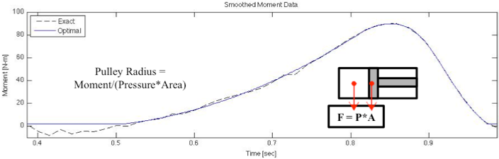
Figure 7: Ankle Moment. This figure shows the exact moment experience at the ankle during normal gait, obtained from David Winter’s Biomechanics and Motor Control of Human Movement, and the optimal moment experienced at the ankle during normal gait (Winter, 2009). The optimal moment is obtained by eliminating the sudden jumps and removing the negative moment values in the exact moment data.
The optimal primary actuator pulley radius was calculated by finding the pressure in the engine as a function of time, from the pressure-volume diagram, and rearranging Equation 4 to solve for the pulley radius. It is important to note that while the pulley radius may change it is always assumed that the edge of the pulley and the AAFO engine are in line with one another. Figure 8 shows the optimal pulley radius as a function of time alongside several constant diameter pulleys. This parametric polar plot of the pulley configuration starts at the green dot and moves along the geometry line with time ending at the red dot.
DISCUSSION
The results of this research show that the modified OTS actuator, which has a theoretical work output of 29.80J with a thermodynamic engine efficiency of 0.61, is able to provide more than enough energy to activate the ankle joint, which makes it an acceptable power source for the AAFO. Using a theoretical P-V diagram (Figure 6), which will be validated with combustion testing, the optimal pulley radius for the plantarflexion phase of the gait cycle was determined. While the optimal pulley radius for the primary actuator was calculated (Figure 8), it has a very complicated geometry.

Figure 8: Optimal Pulley Geometry. This figure shows the optimal pulley geometry as a function of time for the primary actuator of the AAFO.
This complicated pulley geometry stems from three main issues. The first issue is that during the gait cycle the ankle only rotates through a small 27° window. Because the ankle only rotates 27°, only 27° of the pulley perimeter—indicated by the red pie slice in Figure 8—is being used. This results in the squished pulley geometry that is shown. The second major issue is that during the gait cycle the ankle oscillates between negative and positive angle values, resulting in the pulley geometry doubling back on itself. This happens because each time the ankle rotates through a previous degree there is a different pressure in the AAFO engine and a different ankle moment that needs to be matched, resulting in different pulley radii at the same ankle angle. The final complication with the pulley geometry is the extreme pulley radii (2 to 15cm) that are experienced due to the relationship between the engine pressure and ankle moment. Because the ankle moment is such a small value during that beginning of the gait cycle, the radius necessary to match the moment is small, but when the moment reaches its larger values the radii necessary to reproduce this with the engine pressure are very large. It should also be noted that this pulley geometry is specific to the ideal P-V performance of the engine. The optimal pulley geometry will be subject to change when actual engine performance data becomes available through experimental combustion testing.
This paper introduced a unique AAFO design that utilizes a forced-induction, “Walking Engine” system to provide the power for locomotion. The implication of this research is that a modified OTS actuator used as an IC engine is a feasible power source for an AAFO. Providing 29.80J of work output and weighing less than 10oz, this design provides the balance between size and functionality that is not available with current designs. While the optimal pulley radius for the primary actuator was calculated, it has a very complicated geometry. Further research is necessary to determine a practical pulley system, such as a gear or chain torque converter, that allows for the successful implementation of the optimal pulley configuration. This research has laid necessary groundwork for future experiments to further the development of the “Walking Engine” AAFO. This work, characterizing the IC engine and optimizing the pulley radius, will be applied to future research used to construct a fully functional “Walking Engine” AAFO.
ACKNOWLEDGEMENTS
This project was funded by the National Science Foundation (NSF) and the Milwaukee School of Engineering (MSOE) Fluid Power Institute (FPI). A special thanks to Douglas Cook, Vito Gervasi, the Research Experience for Undergraduates (REU) staff, Milwaukee School of Engineering, The Center for Compact and Efficient Fluid Power, the Fluid Power Institute, and all other parties involved, because only with their help was this research possible.
This material is based upon work supported by the National Science Foundation under Grant No. EEC-0540834. Any opinions, findings, and conclusions or recommendations expressed in this material are those of the author and do not necessarily reflect the views of the National Science Foundation.
REFERENCES
Blackwell, D. L., Lucas, J. W., & Clarke, T. C. (2014). Summary health statistics for US adults: national health interview survey, 2012. Vital and health statistics. Series 10, Data from the National Health Survey, (260), 1-161.
Dollar, A. M., & Herr, H. (2007). Active orthoses for the lower-limbs: challenges and state of the art. In 2007 IEEE 10th International Conference on Rehabilitation Robotics (pp. 968-977). IEEE. doi:10.1109/ICORR.2007.4428541
Heywood, J. (1988). Internal combustion engine fundamentals. New York: McGraw-Hill.
Lenhart, R. L., & Sumarriva, N. (2008). Design of Improved Ankle-Foot Orthosis. University of Tennessee Honors Thesis Projects.
Linstrom, P. J., & Mallard, W. G. (2001). The NIST Chemistry WebBook: A chemical data resource on the internet. Journal of Chemical & Engineering Data, 46(5), 1059-1063. doi:10.1021/je000236i
Lusardi, M. M., Jorge, M., & Nielsen, C. C. (2013). Orthotics and prosthetics in rehabilitation. Elsevier Health Sciences. doi:10.1016/b978-1-4377-1936-9.09990-2
Mitchell, R. R., Gallant, B. M., Thompson, C. V., & Shao-Horn, Y. (2011). All-carbon-nanofiber electrodes for high-energy rechargeable Li–O 2 batteries. Energy & Environmental Science, 4(8), 2952-2958. doi:10.1039/c1ee01496j
Winter, D. A. (2009). Biomechanics and motor control of human movement. John Wiley & Sons. doi:10.1002/9780470549148