

Author: Jennifer Cooper
Institution: Clemson University
Date: August 2005
Abstract
Magnetic fields both positively and negatively affect the electron beam orbit in a 100 keV beamline in the Test Lab, Injector Test Stand (ITS) at Thomas Jefferson National Accelerator Facility (Jlab). DC air-core magnets and iron solenoid magnets are used to steer and focus the electron beam throughout the beamline, but time-varying magnetic fields (prominent at power line frequency) adversely modulate the electron beam orbit. We took a number of steps to identify the sources of these fields and engineer a design to shield the beamline. Photographs of a viewer mounted inside the beamline were taken to estimate the displacement of the electron beam due to the varying magnetic fields. In addition, an Extech electromagnetic field adaptor (AC Gauss meter) was used to survey the beamline in a grid-like fashion to identify sources of time-varying magnetic fields (Electromagnetic Field Adapter, Model 480824, Extech Instruments). Non-essential power supplies were turned off and others relocated further away from the beamline. Little improvement was found when non-essential power supplies were eliminated because a power supply located beneath the beamline floor was detected and identified as the dominant source. Different metals, in a variety of shapes and designs, were tested to find the best way to redirect or suppress the fields from the beamline, while not interfering with the function of the DC steering magnets. Mumetal, a magnetic alloy, and enclosed shapes were found to best shield these magnetic fields. Bench tests for engineering solutions showed that by applying mumetal shields around beam pipe and steering magnets, time-varying magnetic fields could be greatly reduced. The time-varying magnetic fields were redirected and decreased the electron beam motion as measured using the viewer, without significantly altering the DC steering magnets.
Introduction
The electron gun group at JLab employs a 100 keV high voltage photoemission gun and beamline to conduct GaAs photocathode lifetime research. Proper use of this test apparatus demands that the extracted electron beam follow a very specific trajectory while en route to the beam dump. The trajectory of the electron beam is determined by a set of beamline elements which induce static magnetic fields for steering and focusing the beam. These include air-core steering magnets, which compensate for the Earth's magnetic field and correct for element misalignment, in addition to an air-core dipole magnet to bend the beam 15 degrees and iron solenoid magnets for focusing the beam. However, time-varying magnetic fields ambient in the vicinity of the beam line (prominent at power line frequency) complicate test apparatus operation because they introduce beam displacement that can cause the electron beam to hit vacuum chamber walls, a condition that degrades vacuum quality and shortens the operating lifetime of the photocathode. Typical sources that cause these time-varying magnetic fields include power supplies, video monitors, fluorescent lights, and electronic controls.
Unfortunately, magnetic fields cannot be eliminated by shielding, only redirected. Thus, certain metals can help redirect these fields away from the electron gun. The magnetic field is proportional to current and weakens with distance. Hence, the farther away the source is from the beamline, the less effect it has on the electron beam orbit (Riley 1995).
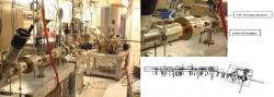
Figure 1. (left) 100 keV electron gun and beamline in the Test Lab, ITS at JLab. (top right) Close up view of DC steering magnets and iron solenoid magnets on the beamline. (bottom right) One hundred keV gun and beamline drawing schematics.
Methods and Materials
An Extech electromagnetic field adaptor (AC Gauss meter) was used to measure the time-varying magnetic fields along the beamline. We measured the field at beamline height (about 4 feet) and performed in a grid-like procedure of 1' x 1' squares. These values were recorded, taking note of areas greater than 3 milliGauss or "hot spots" and other increased areas of magnetic field production. We then took photographs of viewer ITVHG09 mounted inside of the beampipe to determine the displacement of the electron beam. Non-essential power supplies found to be producing elevated time-varying magnetic fields were then either turned off or relocated away from the beamline vicinity in an attempt to lessen the magnetic field. These elements included the cesiator control box, three power stripes, a Pfeiffer turbo molecular vacuum pump, a digital multi-meter, and fluorescent lights. Again, we took photographs of the same viewer to determine if the elimination of these sources had any impact on the electron beam orbit. Only minor improvement was observed. A power supply located beneath the beamline floor of the Test Lab running to the Cryogenic Test Lab (CTL) was detected.
To mitigate a source that cannot be turned off or relocated, such as this, different metals in a variety of shapes and designs were tested to find the best way to suppress the magnetic fields while not interfering with the function of the beamline. Bench tests were performed by sectioning off an area on the floor (8" x 24" was arbitrarily chosen) containing large time-varying magnetic fields. A series of magnetic field measurements at eleven locations (0, 4, 8, 9.25, 10.5, 12, 13.5, 14.75, 16, 20, and 24 inches) were taken with the AC Gauss meter for each material and shape, including the bare floor as a reference. The different materials tested were a 18" x 48" lead sheet, 12" x 28" aluminum foil sheet (folded in half), and a 8" x 25" inch sheet of 0.015 inch thick mumetal made of a high-permeability, magnetically "soft" alloy which contains about 80% nickel and 15% iron (Magnetic Shield Corporation 1997). In addition, the aluminum foil was folded in a "U" shape and tested. After determining mumetal can reduce or redirect time-varying magnetic fields, additional bench tests were performed to find the best and most efficient shape. "Circular", "U", and "L" shapes of mumetal were tested in the sectioned off area, in addition to different configurations of mumetal, including varying the number of mumetal sheets and lifting the mumetal sheet 1 inch above the ground.
After determining the "circular" shape worked best, further tests were performed to see how the mumetal would work directly on the 2.5 inch diameter beam pipe (9 inches long) and to determine if mumetal affects the function of the DC steering magnets and solenoid magnets. The time-varying magnetic field inside of a 2.5 inch diameter piece of beam pipe and iron solenoid (without the magnetic coil) were both measured in the test area with and without mumetal to identify how well the mumetal would actually work on the beamline.
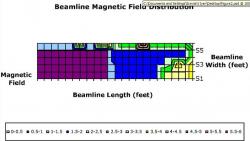
Figure 2. Surface area of the beamline magnetic field distribution measured with the AC Gauss meter.
Next, the DC magnetic field was measured using the F.W. Bell probe. A steering magnet was placed on a 2.5 inch diameter beam pipe and then connected to a power supply. One Ampere of current was directed through the magnet, and the DC magnetic field was measured at five locations (0, 3, 4.5, 6, and 9 inches), 0.5 inches above the ground. After measuring this magnetic reference field, mumetal was wrapped around the beam pipe and the steering magnet was placed on top of the mumetal. The DC field was measured again at the five locations. The steering magnet was then placed on the beam pipe and the mumetal was wrapped around the magnet, and the DC field was measured.

Figure 3. (left panel) Photographs of viewer ITVHG07 mounted inside the beampipe were taken to measure the initial displacement of the electron beam to be 5 mm. The photographs display the election beam at its farthest most points. (right panel) Photographs of viewer ITVHG07 were taken after power supplies were turned off to again measure the displacement of the electron beam. The photographs display the election beam at its farthest points and exhibit a 3.5 mm displacement.
The tests indicated applying mumetal around beam pipe and steering magnets, time-varying magnetic fields could be greatly reduced. Thus, areas of the beamline were wrapped in sheets of mumetal. Approximately 55 inches of the 158.5 inch beamline was shielded with mumetal. Finally, we took photographs of the same viewer after mumetal was wrapped around areas of the beamline to measure the electron beam displacement and observe the decrease in electron beam movement.
Results
The layout of the electron gun and the beamline schematics are shown in Figure 1. The beamline area is 1 foot wide and 26 feet long with a 6' x 8' electron gun table mounted at one end. The air-core steering magnets and iron solenoid magnets are labeled.
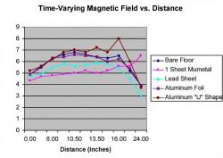
Figure 4. Different materials, including lead, aluminum, and mumetal were tested to find the most efficient material in shielding time-varying magnetic fields. Mumetal proved to be the most efficient.
In Figure 2, the time-varying magnetic field distribution is shown. Elevated fields exist near the side wall, and the "hot spots" are where the three iron solenoid magnets are located. There appears to be a background field of about 2.5 milliGauss along the majority of the beamline.
Figure 3 shows the photographs of the electron beam movement on viewer ITVHG09 at the beam's farthest points (left) and with the cesiator control box, three power stripes, a Pfeiffer turbo molecular vacuum pump, a digital multi-meter, and fluorescent lights turned off and/or located further from the beamline (right). The displacement of the electron beam orbit was measured by comparing the center of the electron beam for each of the photographs. The displacement was measured to be approximately 5 mm in the first case, compared to 3.5 mm in the second, a marginal improvement.
Next, Figure 4 depicts how different metals (lead, aluminum, and mumetal) shield time-varying magnetic fields. A sheet of 0.015 inch mumetal reduces the fields by a factor of nearly 1.5. The lead and aluminum do not appear to shield the fields and the aluminum "U" shape apparently worsens the field.
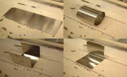
Figure 5. (top left) A sheet of mumetal (8" x 25") was laid over a sectioned off floor area. (top right) Mumetal "circular" shape on sectioned off floor area. (bottom left) Mumetal "U" shape on sectioned off floor area. (bottom right) Mumetal "L" shape on sectioned off floor area.
Figure 5 displays the different shapes of mumetal that we tested, including the flat sheet, "circular" shape, "U" shape, and "L" shape. Figure 6 then reveals the effectiveness of these different shapes. The "circular" shape worked the best in reducing the fields and shielded by a factor of about 3.
Figure 7 (top) shows the time-varying magnetic field measured inside a 2.5 inch diameter beam pipe with and without a mumetal enclosure using the AC Gauss meter. The plot indicates that the metal pipe yields around the same field as the floor, but with the mumetal enclosure, the field decreases by a factor of about 7. Figure 7 (bottom) is a graph of the time-varying magnetic field inside of the iron solenoid magnet with and without a mumetal enclosure. The iron solenoid appears to shield magnetic fields fairly well, and the mumetal only helps by about a factor of 1.

Figure 6. Different shapes of mumetal were tested with the AC Gauss meter to find the most efficient shape for suppressing the magnetic fields. The mumetal "circle" proved to shield best.
Graphs of how the DC magnetic field is affected by the mumetal are displayed in Figure 8. Figure 8 (top) shows that the DC magnetic field inside the 2.5 inch diameter beam pipe is greatly reduced when the mumetal is underneath the steering magnet. When the mumetal is wrapped around the steering magnet, little effect is observed. In Figure 8 (bottom), the DC magnetic field inside an iron solenoid magnet was measured with and without mumetal. The mumetal seemed to decrease the field slightly, although additional tests need to be performed to verify this.

Figure 7. (top) Time-varying magnetic fields were measured inside a 2.5 inch diameter beam pipe (same diameter as the electron gun beampipe) with and without a mumetal enclosure using the AC Gauss meter. (bottom) Time-varying magnetic fields were measured inside the solenoid magnet, both with and without mumetal to see how the actual magnet is affected by the time-varying fields.

Figure 8.. (top) The DC magnetic field was measured inside of the 2.5 inch diameter beam pipe using the F.W. Bell probe. The field was first measured with one Ampere of current directed through the steering magnet, and then mumetal was wrapped under the magnet and then outside of the magnet. (bottom) The DC magnetic field inside of a solenoid magnet was measured. The field was first measured with one Ampere of current directed through the coil and then wrapped with mumetal and measured again.
The areas of the beamline that were wrapped in mumetal sheets can be seen in Figure 9. Areas of pipe and steering magnets were wrapped to cover about 55 of the 158.5 inch beamline. Finally, Figure 10 gives the final photographs of the viewer taken after mumetal was wrapped around areas of the beamline. The displacement was measured to be approximately 1.5 mm, a decrease in the initial electron beam movement by about 3.5 mm.
Discussion
After surveying the beamline for "hot spots" and areas of elevated time-varying magnetic fields, certain non-essential power supplies were identified (a cesiator control box, three power stripes, a Pfeiffer turbo molecular vacuum pump, a digital multi-meter, and fluorescent lights). Turning off the power supplies produced a slight improvement in the displacement of the electron beam orbit. Another area of initial concern was the strong vertical time-varying magnetic field found near the iron solenoid magnets located on the beamline. This concern proved to be unfounded because the solenoid magnets served to shield the beamline from time-varying magnetic fields. Finally, a background time-varying magnetic field of about 2.5 milliGauss was identified. This background field was produced by a power supply beneath the floor, running to the CTL and could not be turned off. For this reason, it was decided that the beamline needed to be shielded.
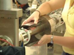
Figure 9. Beam pipe and steering magnets being wrapped in mumetal.
After a number of bench tests, mumetal and enclosed shapes were found to work best in shielding these time-varying magnetic fields that were affecting the electron beam orbit. Surprisingly, a flat, 0.015 inch thick sheet of mumetal did not shield as well as the enclosed shapes of mumetal. This was the case because mumetal can absorb magnetic energy without retaining it but only to a certain degree (Magnetic Shield Corporation 1997). The thicker and larger the mumetal, the better it is at releasing magnetic fields. Enclosing the entire ITS with mumetal was unrealistic, so we decided to shield the beamline directly.
A concern for the function of the beamline was how the steering magnets and solenoid magnets would be affected by the mumetal. The tests proved that mumetal not only shields against time-varying magnetic fields but also DC magnetic fields. The tests also showed that if mumetal were wrapped on the inside of the steering magnets, the DC field was suppressed. If the mumetal remained outside of the steering magnets, however, the DC field was not affected and could still reduce the time-varying fields. The solenoid magnets did seem to be slightly affected by the mumetal enclosure but appeared to shield time-varying magnetic fields fairly well. Easily accessible areas of the beam pipe and steering magnets were wrapped with 0.01 inch thick sheets of mumetal using the "circular" design. We did not wrap the solenoid magnets, in order not to alter their focusing capabilities. Only about one-third of the beamline was wrapped with the mumetal to test the effectiveness of the engineered design.
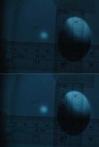
Figure 10. Photographs of viewer ITVHG07 were taken after mumetal was wrapped around areas of the beamline to measure the displacement. The final displacement with 1/3 of the beam wrapped in mumetal was 1.5 mm.
An improvement in electron beam movement was seen after photographs were taken of the viewer with the new mumetal design. There was a decrease in movement by a factor of about 1.4. Another significant finding was that after mumetal was placed on the beamline, the steering magnets required new set points (mainly around zero) because the Earth's DC field was also shielded by the mumetal. By redirecting and suppressing magnetic fields by wrapping mumetal around only certain areas of the beamline, the electron beam movement was decreased without adversely altering the DC steering magnets. Mumetal proves to be effective for shielding both time-varying magnetic fields and DC magnetic fields and could possibly be used to help improve the electron beam orbit of other beamlines that are also being adversely affected by such fields.
Acknowledgements
I would like to thank my mentor Joseph Grames for his knowledge, guidance, and patience, along with the Electron Gun Group for their help and continuous support throughout my internship. Thanks also goes to Bob Rice, an electrician, who helped to identify the power supply running beneath the floor in the Test Lab. I would also like to thank JLab for hosting and sponsoring my research, as well as the United States Department of Energy and Office of Science for giving me the opportunity to participate in this educational and fulfilling SULI program.
References
Magnetic Shield Corporation. (1997). Electromagnetic Shielding.
Riley, K. (1995). Tracing EMFs in Building wiring and grounding. Tucson, AZ: Magnetic Sciences International.