
Author: Ryan Daly
Institution: University of Iowa
Date: November 2006
ABSTRACT
Studies have shown that the use of copepod nauplii as a first feed will increase the survival rate of larvae of several ornamental finfish species, and it is widely agreed that the use of copepod nauplii as a first feed will increase the number of ornamental species which can be successfully cultivated. Many bioreactors have focused on producing live nauplii, but problems arise because the nauplii grow too quickly. To circumvent this problem, we propose a novel airlift bioreactor design to support the collection and preservation of copepod eggs. In most cases, airlift columns are used in bioremediation to suspend pellets for the growth of biofilm. In this case, airlift columns are used to both aerate and to separate copepod eggs from adults into a collection chamber. Computational fluid dynamics (CFD) software was used to simulate the fluid flow in each of two candidate reactors, and dye tracking experiments was used to verify the accuracy of model simulations. One reactor prototype was eliminated because its model could not reproduce the results of dye tracking. The remaining design was modified based on simulation results to produce a new pilot scale prototype.
INTRODUCTION
The marine life fishing industry concerns itself with the non-lethal collection of ornamental fish, marine plants, and invertebrates for live sale to consumers. States such as Florida have set specific limitations on gear, handling methods, and possessions in addition to requiring a saltwater products license (SPL) for those working in the industry. Despite strict regulation, the yearly dockside value of collected species is considerable (US $4.3 million in 1994), and the number of SPL holders has been increasing within the last decade (Adams et al. 2001). However, from 1994 to 1998, the average yearly finfish landing experienced a large decline. Partly because of this, there has been increased concern about the sustainability of certain stocks of finfish obtainable by SPL-licensed individuals (Adams et al. 2001). As a result, the state of Florida has been in the process of revising its laws concerning marine life collection.
The marine collection industry in Florida and its penetrating regulation by the Floridian government are one of many examples that demonstrate the movement toward the preservation of marine habitats and species. Similar restrictions are developing in the Hawaiian islands. This movement has led to an increase in investigation of techniques to cultivate valuable ornamentals such as angelfish (Adams et al. 2001), among others, in order to avoid removal of fish from the environment. For many species, however, there have been complications related to the suitability of live feeds.
The efficiency in cultivation of ornamental finfish has been limited in many cases, such as in that of turbot (Støttrup and Norsker 1997), because of the lack of a suitable live feed for use during the first feeding larval stage of development. Many traditional feeds such as rotifers and brine shrimp nauplii have been shown to be either too large or nutritionally inadequate for use in these circumstances (Ogle et al. 2002). The use of copepod nauplii as a first feed as opposed to other more available feeds has been shown to increase the survival rate of the larvae of some species (Payne et al. 2001). In the finfish cultivation industry, it is strongly felt that their widespread use will make possible the cultivation of ornamentals which could not previously be cultivated.
To promote the use of copepod nauplii, the production rate of copepod nauplii must compete with that of traditional feeds. The most widely used copepod cultivation techniques involve the collection of copepod nauplii directly from batch cultures in which water quality maintenance, nauplius collection, and feeding must be performed manually. In addition, the few available continuous processes utilize expensive computer control equipment, which makes them less attractive to businesses with low budgets. One of the most notable attempts to develop a bioreactor to cultivate copepods was by Støttrup and Norsker (Støttrup and Norsker 1997). They interfaced mechanical devices with computers to allow for events such as copepod feeding and nauplius collection to be performed automatically. However, such a process is not truly a continuous process since it performs automated copepod collections in batches, similarly to batch cultures.
Contributing to the inefficiency and financially infeasibility of cultivation techniques, calanoid copepods such as Bestiolina similis can only be cultured at very low density (Støttrup et al. 1986; Schipp et al. 1999). They also lose their value within hours after collection because they grow to sizes at which they are no longer useful (>80 μm) (McKinnon et al. 2003). For this reason, the collection and preservation of copepod eggs in continuous processes would permit far greater efficiency. One way to accomplish continuous production is to exploit airlift columns (columns of bubble flow through liquid) to induce flow to move copepod eggs from a chamber where the adults live and into a collection chamber where the eggs can be stored at a temperature that arrests development. The prototypes considered in this study resemble three-phase external loop airlift reactors that are commonly used to suspend solid polymer particles for growth of microbial biofilms for the remediation and recirculation of water in aquaculture systems However, in our case, the solid phase consists of microscopic copepod eggs, which are approximately spherical with a diameter of 50μm. Rather suspending the eggs, the liquid flow induced by the bubbles rising through the airlift column moves eggs away from the adults, thereby directing them into a specially designed collection/preservation chamber. The basic motivation behind the use of a bubble column to drive flow is that a bubble column would be a more energy efficient in mobilizing solids, such a small size as eukaryotic cells, than a pump. It also oxygenates the tank. In addition, such a design can be used on a small scale, such as in backyard production facilities.
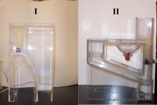
Figure 1: Prototype bioreactors I and II in full operation. In prototype I (left), the adult chamber is the large chamber on the right side of the reactor. In prototype II (right), the adult chamber is smaller and on the left of the reactor. The airlift column on the left side of prototype I is notably connected to the adult chamber by two openings in the wall separating the airlift column from the adults (more visible in Figure 2), whereas in prototype II the airlift column is completely surrounded by four walls.
Two prototype bioreactors, prototype I and prototype II, were developed in our laboratory as possible final designs for a pilot scale production (Figure 1). Prototype I utilizes a single standard bubble rock extending the entire width of the airlift column (i.e., resembling a standard fish tank bubble rock used for oxygenation). Prototype II uses three cylindrical bubble rocks connected to three separate hoses, each attached to the same pump, and extending the entire width of the airlift column, which were sealed in for water tightness using silicon caulk. The pump used in each case was a standard laboratory grade pipette pump. Since each prototype used only one pump (and friction was considered negligible), the airlift column in each prototype effectively received the same power input. The flow medium in each reactor was filtered seawater with an approximate density of 1030 kg/m3. Prototype II more closely resembles an external loop airlift bioreactor than does prototype I because it makes use of a true external loop, which is characterized by a complete separation of the airlift column from the medium on the other side of the loop. In contrast, the airlift column in prototype I is connected to the adjacent chamber. Therefore the most basic difference between the two prototypes is the situation of the airlift column.
In this study, the two prototype bioreactors were modeled using computational fluid dynamics (CFD) methods, and their predictions were evaluated using dye experiments. . CFD modeling of the flow field in prototype II showed promising correlation with experimental data, which we attribute to the isolation of the bubble flow to within a more confined space. Prototype II was tested for egg collection efficiency using copepod eggs and was found to achieve a 70% collection efficiency. The results of the simulations on prototype II also indicated that changing the location of the collection chamber and the baffle at its entrance could increase egg collection efficiency. The best design was taken to be that which maximized the flow stagnation within the collection chamber. Modifications to the design were made and simulated in order to produce an improved final design to maximize egg collection efficiency. That design was scaled up to pilot scale and its flow fields tracked with dyes.
MODEL DEVELOPMENT AND VERIFICATION
Overview
Computational fluid dynamics methods are commonly used to predict fluid flow patterns in single phase systems but less commonly in multiphase systems (Bertola et al. 2003; Jakobsen et al. 1997). Such methods require solving very large systems of partial differential equations (PDEs) based on conservation laws such as the conservation of momentum and the continuity equations of fluid flow. Because of this, the airlift columns of prototypes I and II can be challenging to model. Computational software programs such Femlab have been developed to model systems described by these equations. Specifically, Femlab allows the input of geometries, specification of fluid properties of regions in these geometries, specification of mathematical conditions/simplifications at regional boundaries, and specification of driving forces acting on the fluids in different regions.
Model development
The 3-dimensional Navier-Stokes application within Femlab was used to simulate the fluid flow fields in each prototype. The exact dimensions of each were manually reproduced in schematic diagrams and these geometries were then used to create exact replicas in Femlab. As each prototype is symmetrical about a plane, the cross sections of each were drawn in two dimensions first, and were then extruded to the correct depths by using the Extrude feature. Additional drawing planes were created to input and extrude the finer details of the structures.
Additional subdomains were created in each prototype in order to model the airlift columns. For prototype I, a rectangular box was drawn within the airlift column to represent a region that contained the majority of the two-phase flow, and to represent the majority of the region in which momentum transfer between the gas phase and the liquid phase would be occurring. A smaller rectangular subdomain was used to represent the airlift region because it was observed that the two-phase flow did not completely consume the airlift column when the prototype was in operation (see Figure 2). The airlift column in prototype II was also represented with a rectangular box. However, in this case the region of two-phase flow completely consumed the airlift column, and thus its boundaries were appropriately represented by the physical boundaries of the reactor (see Figure 2). In each two-phase region, a volume force was input in the direction against gravity using settings in the Subdomain Settings menu. Trial and error was used to determine the value of the volume force that would give maximum fluid velocity values of around 2 cm/s.

Figure 2: The Femlab models of each prototype reactor and the two-phase regions. The two-phase regions are defined to model the buoyant driving force of the bubble flow on the saltwater medium and can be seen in each model as rectangular boxes within the airlift columns. The presence of the two openings connecting the airlift column to the adult chamber in prototype I is likely responsible for the disparity between flow fields determined through dye experiments and through simulation in prototype I.
The boundary conditions used can be generalized as follows. All external surfaces were given the no slip boundary condition, which is the assumption that fluid flow velocity at the indicated surface is zero, and all internal surfaces representing a boundary between the region of two-phase flow and one-phase flow were given the neutral boundary condition, meaning that the flow medium is free to pass across it.
The solve methods used also varied, but were limited to steady state solutions only. Time dependent solutions were not attempted due to limitation in computational power.
Model verification
Flow field information obtained from dye experiments were compared against model predictions to ascertain whether the model was able to adequately describe the fluid flow fields, and thus verify that our approach to model the two-phase region in the airlift column was successful. A successful verification was taken as reasonable similarity between the model-predicted fluid flow fields and the observed flow of the dye immediately after its introduction into the fluid. For each prototype reactor, the flow regimes were observed to change very little with respect to variations in the volumetric flow rate of gas introduced to the bubblers. Therefore, dye tests were executed at an arbitrary volumetric flow rate of about 7 ml/s. In each prototype, methylene blue dye was added at the top and center of the adult chamber. A camera was used to take a video recording of the path of the dye flow for prototype II to allow for comparison to the model.
RESULTS
Prototype Simulations

Figure 3: The flow fields of prototypes I and II as predicted by Femlab. The flow field shown for each prototype model is represented by both a directional vector field (a directional arrow at each point) and a color map representing the relative magnitudes of the velocity at each point.
Figure 3 summarizes the results of fluid flow simulations for prototypes I and II using the developed Femlab geometries in Figure 2. It was found that in solving for the flow fields in both models, certain mesh settings had a tendency to produce singular matrices resulting from empty pressure values at specific points in the reactor, usually points at sharp edges in the geometry. Such failures were probably due to the divergence of the integration algorithm. Consequently, some problems, which resulted in singular matrices at a dense mesh setting, did not result in singular matrices at a sparser mesh setting. As such, the mesh settings had to be varied and optimized to the highest possible density such that the computer had adequate memory and the mesh did not result in divergence of the integration algorithm. It was necessary in the case of prototype II to round off some of the sharp edges to avoid divergence due to discontinuity of the boundary. The modifications are not visible in Figure 2 due to the small scale on which they were drawn.
Comparison to Dye Tracking
It was found that model predictions for both prototypes were reasonably close to the profiles given by dye experiments with the following limitations. The dye tracking experiment for prototype I showed more turbulence than was expected when compared to the simulation. This was likely because the two-phase region of bubble flow did not completely fill the airlift column. Poor bubble containment allowed for bubble coalescence and less predictable behavior even in regions outside the bubble column. As a result, the goal to localize turbulence was not achieved. The model for prototype II showed much better correlation to dye tracking. This was a consequence of the fact that bubble coalescence, and hence turbulent energy dissipation, was limited because the two-phase region was well contained in the airlift column. Good bubble containment also guarantees a more uniform bubble size and density, and thus assures that the power imparted to the flow medium from buoyant bubble rise is nearly uniformly distributed and all in the direction against gravity. Therefore the volume force approximation was found to be reasonable for the model of prototype II, but not for the model of prototype I.
New Designs
Prototype II was selected and model simulations were used to propose design modifications that would allow the fluid to be more conducive to sequestering the eggs to the egg collection chamber. Models with the egg collection chamber in three different locations along the lower arm of the reactor were simulated (see Figure 4). Little change in the flow field solutions were noticed among the three models. As a result, the model in which the egg collection chamber was placed closest to the adult chamber was used because it minimized the distance the eggs were carried, which in turn minimized the amount of surface area to which the eggs could adhere to on their way down. To influence fluid flow inward, the shape of the collection chamber was modified by adding volume to the front of the entrance chamber. A baffle was also added to the entrance of the collection chamber in order to increase the velocity of the fluid entering the chamber, presumably giving the eggs enough momentum to pass into the chamber and to overcome exit flow. Two different baffle locations were tried. The baffle location closer to the entrance edge was chosen on the basis that it increased entrance fluid velocity and decreased exit fluid velocity. As a final measure, the shape of the baffle was curved to influence the flow of eggs more downward, ensuring their placement on the bottom of the chamber. The final proposed design is shown in Figure 4.

Figure 4: Dye tracking studies of the revised prototype II built to a 15 liter pilot scale reactor. Photos courtesy of Kyle Vanderlugt.
The prototype shown in Figure 4 was scaled up to pilot scale. Figure 6 shows dye studies of the fluid flow pattern for a single aeration rate (~ 0.3 cm s-1). Clearly, the dye shows that the fluid flow field follows the predicted pattern, rapidly increasing in velocity upon its entrance to the chamber and slowing significantly at the lower depths of the egg collection chamber (Table 1). The dye tests show a clear dead zone in the middle of the egg collection chambers, as predicted by the model. As can be expected, the flow stagnation demonstrated by the dye study was accompanied by some minor turbulence, possibly due to more complex molecular interactions not part of the CFD simulation. These results have verified the success of the model predictions and have spurred new research into the use of solid substrates placed at the bottom of the egg chamber to which the eggs will attach and be immobilized.
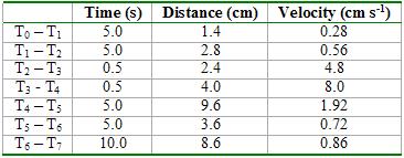
Table 1: Dye tracking data for the 15 liter pilot scale bioreactor fabricated from the revised designed of prototype II.
DISCUSSION
The models and boundary conditions used in the prototype simulations, as well as in the new designs, limits the model' ability to predict realized flow fields. First, the air-water phase boundaries at the top of each reactor (where the medium is open to the atmosphere) were simulated as solid boundaries and thus not accounted for. Comparison between the model and dye tracking information for prototype II, for example, showed a weak circulation pattern in the adult chamber that did not appear in the simulation to a noticeable extent. This is because the air boundary is not solid and suggests the no slip condition is not a good assumption for a boundary of air. However, this particular deviation from the dye tracking experiment proved to have little effect on the flow fields elsewhere in the prototype, particularly near the egg collection chamber, which is the subject of primary interest. The model developed for prototype I likely deviated from the dye tracking experiments because the geometric configuration of the airlift column itself was irregularly shaped, which resulted in unpredictable flow patterns that depended heavily upon finer details of the structure, such as the rounding of sharp edges.

Figure 5: The flow solution given by Femlab for the new prototype design. A close-up view of the egg collection chamber in the redesigned prototype demonstrates the prediction that eggs will enter at a high velocity but will quickly be decelerated to remain in the chamber.
Figure 5 presents the fluid flow fields in the collection chamber of the revised design. The simulation clearly shows that the fluid velocity, and therefore the momentum imparted to the eggs, is concentrated at the entrance to the collection chamber where the flow is mostly downward. In addition, the exit fluid momentum is at a minimum, which is indicated by the high concentration of dark blue at the exit. The overall result is that the eggs are given a large initial momentum into the collection chamber and downward toward the bottom where the magnitude of fluid velocity is nearly zero. This has the effect of directing the eggs toward the bottom of the chamber and with enough momentum to possibly overcome the much weaker fluid flow pulling them out upward. The final redesign of prototype II makes use of controlled fluid flow to direct egg deposition rather than relying mostly on their slightly negative buoyancy to land in the collection chamber. To our knowledge, this is the first such reported use of the airlift design, which has traditionally used airlift to suspended solid particles such that the liquid fluid is brought into contact with the solid suspensions. The fact that the fluid flow fields were reasonably confirmed by dye tracking experiments in a pilot scale reactor of the same dimensions (Figure 6, Table 1) suggested good correlation between model predictions and experimental observation.
CONCLUSIONS
The collection and preservation of the copepod egg rather than the nauplius is an important advancement and if properly used, could lead to an economical method to produce copepod nauplii in large numbers to permit the cultivation of previously uncultivable ornamental fish. This study is one of the first proposed continuous processes aimed at a simple and cheap solution to the problem of cultivating copepods continuously. The motivation behind the development of a simple economical continuous bioreactor to produce copepods of proper maturity in a process free of the need for separation of nauplii from eggs, and free of the need for computer control to effect automation, is to allow for both small and large scale production of one of the most effective first feeds for ornamental finfish currently known. Such a process has the potential to expand the marine life collection industry while encouraging the conservation of the wild ornamental population.
ACKNOWLEDGEMENTS
Funding for this work was provided by NSF and DOD through NSF grant #02-43600. The author would like to also thank the University of Hawaii Sea Grant College program for its support of the MSURF program and Kyle Vanderlugt for his copepod expertise and help in prototype testing.
REFERENCES
Adams, CM, SL Larkin, and DJ Lee (2001) Volume and Value of Marine Ornamentals Collected in Florida, 199098. Aquarium Sciences and Conservation 3: 25-36.
Bertola, F, M Vanni, and G Baldi (2003) Application of Computational Fluid Dynamics to Multiphase Flow in Bubble Columns. International Journal of Chemical Reactor Engineering.1: A3.
Jakobsen, HA, BH Sannæs, S Grevskott, and HF Svendsen (1997) Modeling of Vertical Bubble-Driven Flows. Ind. Eng. Chem. Res. 36: 4052-4074.
McKinnon, AD, S Duggan, PD Nichols, MA Rimmer, G Semmens, and B Robino (2003) The potential of tropical paracalanid copepods as live feeds in aquaculture. Aquaculture. 223: 89-106.
Ogle, JT, C Nicholson, and JM Lotz (2002) Culture of the copepod Acartia tonsa utilizing various artificial feeds. Gulf and Caribbean Fisheries Institute. 53: 234-240.
Payne, MF, RJ Rippingale, and JJ Cleary (2001) Cultured copepods as food for West Australian dhufish (Glaucosoma hebraicum) and pink snapper (Pagrus auratus) larvae. Aquaculture. 194: 137-150.
Schipp, GR, JMP Bosmans, and AJ Marshall (1999) A method for hatchery culture of tropical calanoid copepods, Acartia spp. Aquaculture. 174: 81-88.
Støttrup, JG, and NH Norsker (1997) Production and use of copepods in marine fish larviculture. Aquaculture. 155: 231-247.