
Andrew Chan, Jacob Altholz, Richard Weir, Matthew Davidson
Department of Bioengineering, University of Colorado Denver. MSC 185. 1200 E. California Blvd. Pasadena, CA. 91126.
Department of Bioengineering, University of Colorado Denver. 12705 E. Montview Ave., Suite 100. Aurora, CO 80045-7109.
ABSTRACT
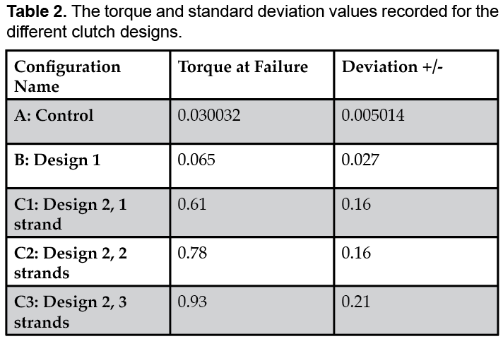
The standard motors that drive prosthetic fingers cannot provide both the speed and torque required to hold objects as efficiently as a human hand. This problem of high speed/torque can be solved by using multiple motors or transmissions to drive a prosthetic finger, but these increase weight, cost, and complexity of the prosthetic finger system, which lead to people abandoning their device. Presented here is a novel clutch mechanism that alleviates the high speed/torque problem by holding the motor in place during gripping using nickel-titanium “memory wire” called Flexinol. This clutch mechanism allows an inexpensive low-torque motor to drive fingers while retaining the grip strength benefits of a high torque motor thus reducing cost and weight of the prosthetic finger system. The newly developed clutch presented in this paper was compared to our earlier nitinol clutch design (described in Altholz et al., 2015) and to a clutchless motor, which served as the control. The direct effect on torque resisted using one, two and three strands of Flexinol within the new clutch design was measured in addition to the torque resisted by the alternate clutch designs. The maximum torque each clutch could withstand before failure (forced motion) was found by applying a torque to the motor with a weighted bar. The clutch design presented in this paper resisted significantly more torque than the older clutch and the control system (p < 0.001). Increasing the number of nitinol strands also increased the torque the clutch could provide. Clutch 2 with three strands of nitinol had a failure torque of 0.93 with a standard deviation of ± 0.21 Nm. This is a torque that is significant enough to withstand forces encountered in by prosthetic users and is within a margin of error of the industry standard minimum torque of 1 Nm. Therefore, our novel clutch can resolve the high-speed/high torque problem while reducing cost and weight.
INTRODUCTION
The earliest known prosthetic hands originated in ancient Egypt (Zuo and Olson, 2014). These early designs were mostly cosmetic representations of hands and provided little functionality (Zuo and Olson, 2014). Systems using cables as actuators emerged in the late 1700s and became commercially available in the mid-1800s (Zuo and Olson, 2014). These prostheses allowed the user to open or close a gripping hand by pulling a cable with the opposite arm. Cable-driven systems are frequently used due to their low cost and mechanical simplicity, but the repetitive motions required to operate them can lead to over-use shoulder injuries (Weir, 2004). The first motor-controlled devices were invented in the early 20th century and have seen dramatic improvements in recent years. The most advanced of these devices, myoelectric prosthetics, can respond to signals from muscles in the remaining limb to control anatomically similar fingers to grip many different objects (Geethanjali, 2016). However, as dexterity and strength increase, so do weight, complexity, and cost.
An intact hand picks up an object in two phases: a high-speed, low-torque reach phase where the hand is moved to the object, and a low-speed, high-torque grasp phase where the hand conforms to the object and applies appropriate force (Weir, 2004). Prosthetic devices, however, must strike a balance between efficiency and functionality (Weir, 2004). Motors in a prosthetic hand can recreate this grasping process using a low-torque/high-speed motor during the reach phase and high-torque/low-speed motor during the grasp phase (Weir, 2004). However, this requires an engineering choice as a single system cannot satisfy both of these torque/speed constraints: 1) including both motors which is effective but increases weight and cost 2) using only a high-torque motor which allows for grasping and lifting of heavier objects but is slow and draws more power, and 3) using low-torque motors that are inexpensive and quick, but can be easily driven in the opposite direction even when engaged, making it difficult to hold heavy objects. Typically, the industry standard is to sacrifice weight for effectiveness which can often lead to device abandonment (Weir, 2004). The negative consequence of the third design choice is known as “back-driving” and is a major issue for prosthetic devices. Optimizing this choice to limit the ability of motors in a prosthetic hand to be back-driven is essential for designing effective prosthetic devices.
The solution presented here is a mechanism that grasps the motor drive shaft like a clutch to prevent back-driving when subjected to forces that someone would encounter in every-day life. While purely mechanical clutches exist, they are complex, heavy, and expensive, and usually do not allow the user to control when they activate. Therefore, this clutch uses nitinol “memory wire” which contracts to actuate a simple caliper system and could be controlled by the prosthesis’s existing electronics. Including a clutch overcomes the major limitation of high-speed/low-torque motors: their back-drivability. The back-drivability refers to the extent to which the motor can be driven in the reverse direction. It also reduces weight and complexity and only costs about $10 to manufacture. To our knowledge, it has not been previously used in the specific application we describe in this paper.
Presented here is analysis of two nitinol-activated clutch designs using different numbers of nitinol strands. This new clutch design prevents back-driving better than both an unclutched motor and the clutch described by Altholz et al. (2015). Altholtz et al. introduced a basic nitinol-actuated clutch design with demonstrated minimal functionality. This paper expands on their results by demonstrating that a low-torque motor can have the low back-drivability benefits of a high-torque motor when combined with the new clutch. Integrated into prosthetic hands, this new design could reduce cost and weight in commercial prosthetics. The new clutch was tested with one, two, and three nitinol strands. The authors of this study hypothesized that increasing the number of strands would increase the amount of torque the clutch could resist. Since the force of friction is linearly correlated with the applied normal force (Ff = µFN), and each strand applies force independently, the resistive increase from adding more strands was expected to also be linear.

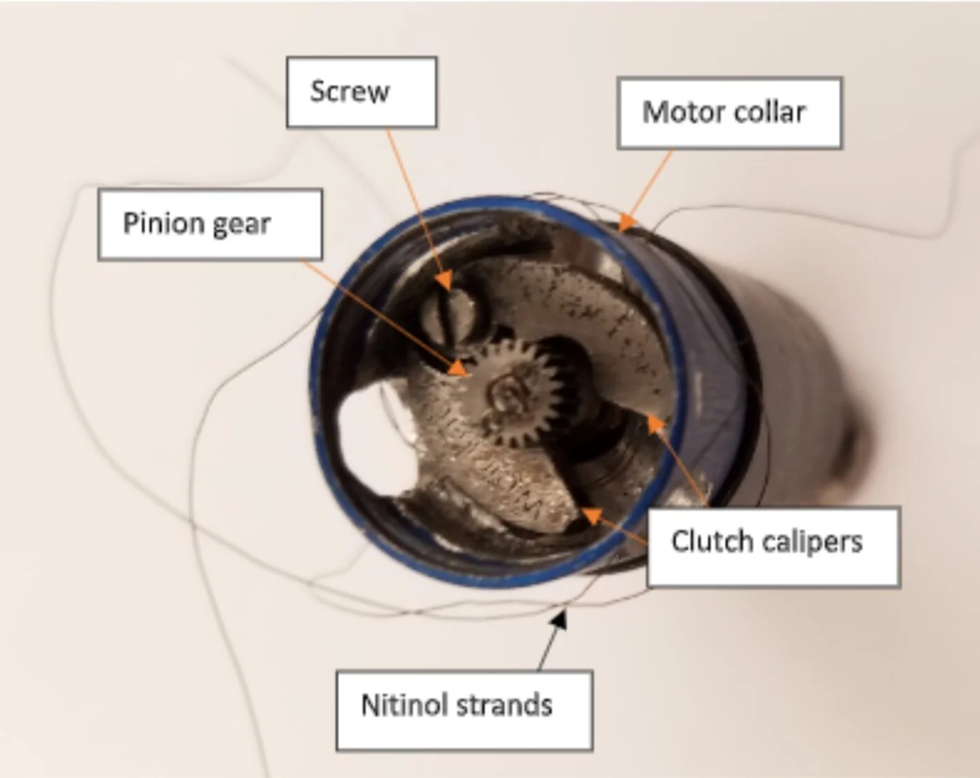
Figure 1. Clutch calipers placed inside the motor collar and threaded with a single strand of nitinol wire wound around the outside of the calipers and through the open hole in the motor collar. The housing was modified to accommodate the size of the calipers and to allow the wire to exit the housing (to the right of the screw in the figure). The calipers were machined to slip-fit tolerances to fit below the pinion gear.
METHODS
The clutches presented here work by using “nitinol memory wire”, an alloy of nickel and titanium that can be bent and twisted holding its shape like a normal wire (e.g. copper or aluminum), but that returns to its original shape when electricity is applied to it (Khan, Muhyuddin, and Wadood, 2017). This clutch uses a proprietary brand of nitinol, called Flexinol, that contracts when subjected to a low-voltage current instead of simply returning to a user-set shape (DYNALLOY, n.d.- a).
The Flexinol was wrapped around two semi-circular metal calipers around the motor shaft so that, when current was applied to the wire, the calipers contracted and applied force to the motor shaft to hold it in place (Figures 1 and 2a). This allows a prosthetic hand to maintain a grasp on heavy objects even when using a low-torque motor. Flexinol was chosen for this study because it is the industry standard for contractile wires, and the only brand for which technical specifications are available. In addition, using commercially available components when available reduces cost ($4.50 / meter (DYNALLOY, n.d. -b) compared to a custom manufacture process), improves test repeatability, and scales for mass production. Designing and manufacturing novel memory wire was beyond the scope of this project and the capabilities of this lab.
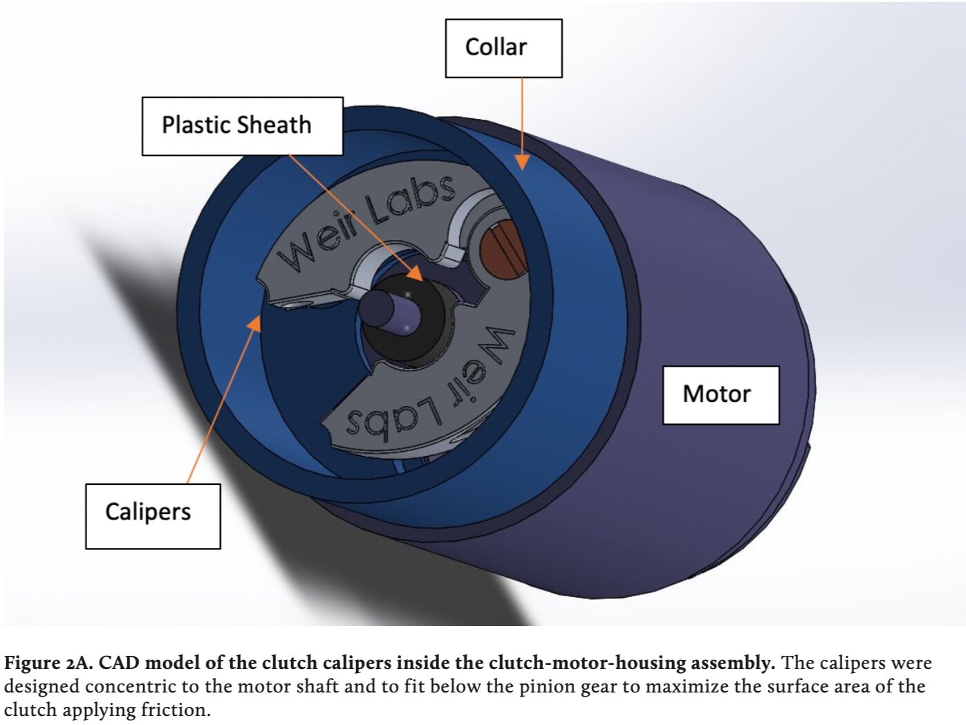
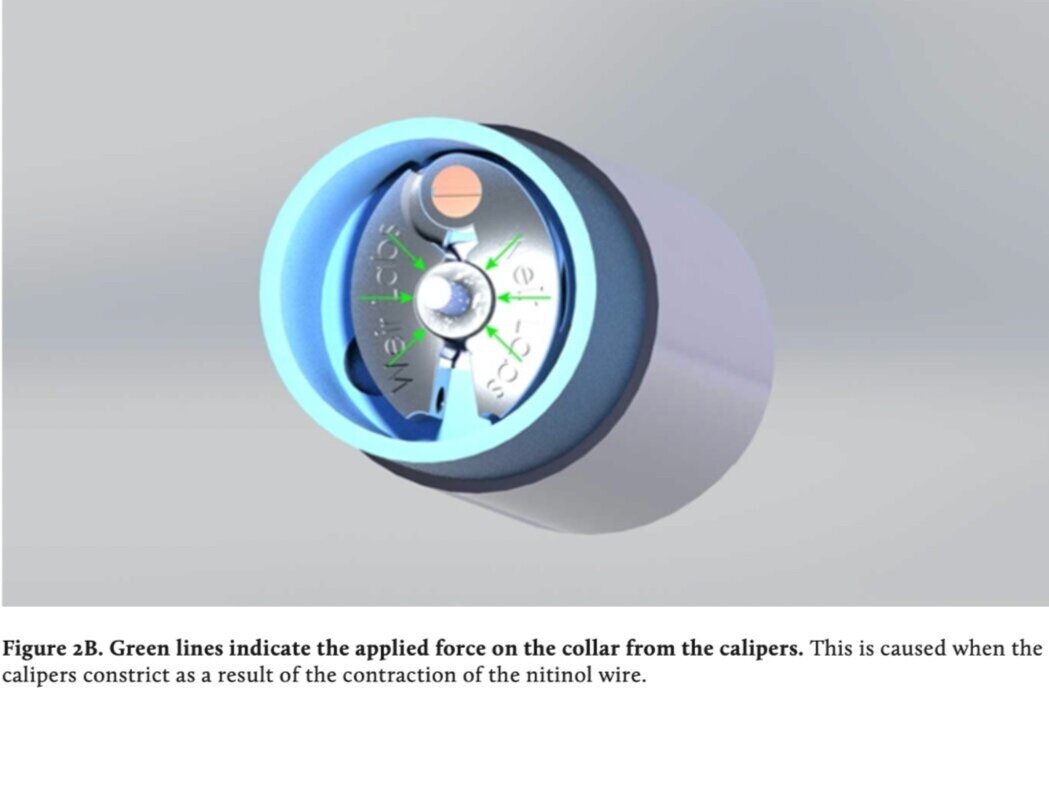

Figure 3. The complete testing assembly picturing the secured motor with clutch enclosed. The motor had to be secured by two clamps to prevent it rotating in relation to the gearbox. The wire was clamped between two nuts for ease of testing.
Design and fabrication

Figure 4A. A side by side comparison between clutch design 1 and clutch design 2. Clutch design 2 is thinner, concentric to the drive shaft, and contains a concentric clutch, a thinner outside housing, and a large hole through the center, that make it easier to manufacture and assemble.

Figure 4B. A comparison of all three clutch designs to indicate the evolution in design over the three iterations (from left to right, Altholz Clutch, Clutch 1, Clutch 2).
The clutch calipers were designed with Solidworks CAD software (Dassault Systemes, Vélizy-Villacoublay, FR) and 3D printed out of tool grade, high nickel content steel using an EOS M270 printer (EOS, Krailling, GR). They were fabricated on a CNC mill at the University of Colorado at Denver machine shop to remove support material. The calipers were attached to the motor housing by a screw and fit around a plastic sheath on the drive shaft (Figures 1 and 2). A polyethylene plastic was chosen for the sheath to minimize cost and improve durability. Since the collar was not in contact with the nitinol, there was no concern that any heat from the wires would damage it. However, a commercial design should consider an even more durable material. All tests were performed with a Faulhaber MM1724 DC motor (Faulhaber, Petersburg, FL) the collar of which had been modified to accommodate the clutch. A 0.4 mm Flexinol wire (DYNALLOY, Irvine, CA) was threaded through the calipers and out through a hole in the motor collar. This wire was secured to two bolts in the test support (Figure 3). Current was provided by a power supply (BK Precision 1666) set to provide 5 V and limited to 1000 mA. Current passed through the Flexinol caused it to contract the calipers around the drive shaft. The test configurations are shown in Figure 4 and described in Table 1.
Configuration A served as a control to test the system with no clutch. Configuration B tested the clutch described in Altholz et al. (2015), which had non-concentric calipers and used one strand of Flexinol. The configurations of C used Clutch 2 which included concentric calipers, a plastic collar around the motor shaft, and a washer between the clutch and the gear box to prevent jamming (Table 1). Configuration C was tested with one, two, and three strands of Flexinol. At three strands, current draw exceeded 1000 mA and overheating became a concern, so no additional strands were tested.

There is no formally established benchmark for motor torque in the literature. Although some prosthetic hands produce as much as 2.5 Nm torque at the metacarpophalangeal joint (knuckles), 1 Nm was chosen as the minimum torque criterion because it is the industry standard used for the German-developed DLR/HIT Hand II (1.05 Nm) and the prosthetic devices from Liu et al. (2008).
Experimental techniques

Figure 5. A simplified drawing of the testing setup depicted in Figure 3.
This test was intended to mirror forces that a prosthetic user would need to exert during activities of daily living. To measure torque at failure, the clutch and motor were secured to the lab bench with rubber-padded metal clamps and a 0.28 m long hardened steel bar weighing 105.28 g was attached to the motor shaft with a set screw 2 cm from its end (Figure 5). Hardened steel was used to eliminate any bending effects from the measurements. The strength of the motor-clutch assembly was measured by attaching the bar to the output shaft and rotating it until it fell, at which point the angle was recorded. Angles were measured by hand with a goniometer. Each trial was performed 10 times.
Torque at failure was calculated from the mass and angle of the bar by
τ = l⁄2 F sin (θ) (1)
where l is the length of the bar from the pivot point (0.25 m) and F is the mass of the bar multiplied by g, acceleration due to gravity, and θ is the angle at failure.
The new clutch overcame the maximum torque the bar could provide alone. Therefore, to find the maximum torque, a cup was attached 0.24 m from the pivot point and lead shot was slowly added in approximately 0.5 g increments until the clutch failed and the bar fell. The total mass of both the cup and the added lead was recorded at failure. The bar was set in position before the clutch was engaged. Torque was calculated according to the following equations
τbar = (lbar ⁄ 2) x F1 (2)
τcup = lcup x F2 (3)
τnet = τbar + τcup (4)
where Ibar is the length of the bar (0.25 m), Icup is the distance of the cup from the pivot point (0.24 m) and F1 is the mass of the bar multiplied by the acceleration due to gravity (g) divided by two. F2 is the mass of the cup and added mass multiplied by the acceleration due to gravity (g) divided by two.
Analysis
The failure torque in different configurations was compared using a one-way ANOVA with a significance threshold of p < 0.05. Following this, Tukey’s honest significant difference (HSD) test was performed at a significance threshold of p < 0.05 to determine the differences between each of the five configurations (Table 1).

Figure 6. Comparison of the torque of the different systems and statistically significant differences which are indicated by the stars. There was no significant difference between the torque for the unclutched system and design 1, nor was there between design 2 2-strand and design 2 3-strand. All other combinations experienced significant differences.
RESULTS
The maximum failure torque of each configuration and clutch design is shown in Figure 6. Important key results are described below.
A one-way ANOVA indicated that Clutch 1 did not significantly increase maximum torque compared to the unclutched system. The failure torque of Clutch 2 was higher than both the unclutched system and Clutch 1 (Tukey HSD). Within Clutch 2, one-strand and two-strand configurations performed similarly (better than Clutch 1 and the unclutched system), as did two and three strand configurations. The three-strand configuration had a significantly higher failure torque than the one-strand configuration (Tukey HSD). Error was calculated using the ANOVA test.
A linear relationship was found between torque and number of strands of Flexinol (R2 = 0.9964).
DISCUSSION
Clutch 1 did not perform as well as anticipated. The average 0.079 Nm of torque was far from the desired 1 Nm and there was no significant difference between the Altholz clutch and the unclutched system. The key deficiency of this design was that the calipers were not concentric with the drive shaft, resulting in a single point of contact and reducing the applied friction. This demonstrates that Clutch 1 would not be effective in a real-world scenario as it was not a significant improvement over the unclutched motor. Additionally, Clutch 1 was prone to jamming due to its large caliper size.
Clutch 2 was a significant improvement over Clutch 1 and the unclutched system (Figure 3). The greatest failure torque was found in the two and three nitinol strand configurations of the new clutch. Creating concentric calipers and adding a plastic collar to the drive shaft allowed the system to resist 0.93 Nm ± 0.21 Nm of torque at failure with three strands of Flexinol. This meets the requirement for resisting real-world torques and appears to be the maximum torque achievable with the current design.
The Effect of Increasing Strands
Increasing the number of strands of nitinol linearly increased the maximum torque by 0.16 Nm per strand (R2 = 0.996). However, two factors limit further increasing the number of strands. First, increasing strands also increased the current draw. While current draw was not measured during the testing (it was regulated to 1000 mA), it was noted that the unregulated current draw with three strands was over the power supply limit of 1000 mA. This heated the wires to the point of becoming incandescent In contrast, one strand drew only about 200 mA. With more wires, there is concern that the nitinol would reach the temperature at which it could melt or interfere with other components of the prosthetic system.
Second, increasing the number of strands noticeably increased the time it took for the wires to cool enough to relax the clutch system. This time measurement was not part of the experimental design but was estimated to be shorter than one second with the other configurations and about four seconds with three strands. This is likely too long to be useful in a prosthesis since people need to be able to release objects quickly.
Conclusions
This study has shown the simplicity and effectiveness of a nitinol clutch system to prevent back-driving in motors for prosthetic hands. The three-strand Clutch 2 resisted 0.93 ± 0.21 Nm of torque, which achieved the goal of 1 Nm. The calipers were easy to manufacture and implement, and the cost of materials was very low (approximately $10 per unit). The rest of the system was comprised of parts that are commercially available. As such, this clutch would be a viable option for large-scale production and use.
This study shows for the first time that nitinol wire clutch systems could have a promising future in prosthetics. Building prosthetic fingers that can be driven using inexpensive low-torque motors while still being able to grasp heavy objects will improve functionality and reduce abandonment rates.
Two additional targets for improving this clutch design are: the motor shaft coating and the Flexinol wire thickness. In this design, the motor shaft collar was made of SLA cured resin plastic. Although this coating survived the testing without incident, a collar made of a more durable material, such as a metal, could increase the friction and therefore the amount of torque resisted. Second, increasing the thickness of the wire could increase torque by providing a greater applied force to the central drive shaft. This additionally could resolve the current draw and reaction time limitations.
ACKNOWLEDGMENTS
Authors would like to thank Jac Corless and Stephen Huddle for their assistance in the manufacture and machining of the clutch calipers and housing.
REFERENCES
Altholz, J., Huddle, S., and Weir, R. (2015). Development of a Clutch Mechanism to Combat Prosthetic Backdrivability. Research and Creative Activities Symposium. Denver, CO.
Biddiss, E., Beaton, D., and Chau, T. (2007). Consumer design priorities for upper limb prosthetics. Disability and Rehabilitation. Assistive Technology, 2(6), 346–357, available: https://doi.org/10.1080/17483100701714733.
Cragg, A., Lund, G., Rysavy, J., Castaneda, F., Castaneda-Zuniga, W., and Amplatz, K. (1983). Nonsurgical placement of arterial endoprostheses: a new technique using nitinol wire. Radiology, 147(1), 261–263, available: https://doi.org/10.1148/radiology.147.1.6828742.
Dotter, C., Buschmann, R., Montgomery, K., and McKinney, J. (1983). Transluminal Expandable Nitinol Coil Stent Grafting: Preliminary Report. Radiology, 147, 259–260, available: https://doi.org/10.1148/radiology.147.1.6828741.
DYNALLOY. (n.d.-a). Flexinol® Actuator Wire Technical and Design Data. Retrieved August 13, 2017, from http://www.dynalloy.com/tech_data_wire.php.
DYNALLOY. (n.d.-b). Introduction To FLEXINOL® Actuator Wire. Retrieved August 13, 2017, from http://www.dynalloy.com/flexinol.php.
Geethanjali, P. (2016). Myoelectric control of prosthetic hands: State-of-the-art review. Medical Devices: Evidence and Research. https://doi.org/10.2147/MDER.S91102.
Okamura, H., Yamaguchi, K., and Ono, R. (2009). Light-Driven Actuator with Shape Memory Alloy for Manipulation of Macroscopic Objects. International Journal of Optomechatronics, 3:4, 277-288, available: https://doi.org/10.1080/15599610903391150.
Hoh D. J., Hoh B. L., Amar A. P., Wang M. Y. (2009). Shape memory alloys: metallurgy, biocompatibility, and biomechanics for neurosurgical applications. Neurosurgery, 64(5):199–214, available: https://doi.org/10.1227/01.NEU.0000330392.09889.99.
Khan, A. N., Muhyuddin, M., and Wadood, A. (2017). Development and characterization of Nickel--Titanium--Zirconium shape memory alloy for engineering applications. Russian Journal of Non-Ferrous Metals, 58(5), 509–515, available: https://doi.org/10.3103/S1067821217050078.
Koh J.-S. (2018) Design of shape memory alloy coil spring actuator for improving performance in cyclic actuation. Materials,11:2324, available: https://doi.org/10.3390/ma11112324.
Liu, H., Wu, K., Meusel, P., Seitz, N., Hirzinger, G., Jin, M. H., Liu, Y. W., Fan, S. W., Lan, T., and Chen, Z. P. (2008). Multisensory five-finger dexterous hand: The DLR/HIT hand II. In 2008 IEEE/RSJ International Conference on Intelligent Robots and Systems, IROS (pp. 3692–3697), available: https://doi.org/10.1109/IROS.2008.4650624.
Weir, R. (2004). Design of Artificial Arms and Hands for Prosthetic Applications. In Standard Handbook of Biomedical Engineering and Design (pp. 1 – 61).
Weir, R. (2004). Standard Handbook of Biomedical Engineering and Design (pp. 32.1 – 32.61).
Zuo, K. J., and Olson, J. L. (2014) “The Evolution of Functional Hand Replacement: From Iron Prostheses to Hand Transplantation.” Canadian Journal of Plastic Surgery.